- 31 - 115.6031.0
Although the Vaporizer may be operated at any temperature up to 205°F. It is recommended that the Vaporizer be
disassembled, cleaned and inspected when the heater Duty Cycle reaches 90%, even if the operating temperature is
less than 205°F.
The Duty Cycle may be timed using a stopwatch or equivalent and is determined as follows:
On Time + Off Time = Total Time
Duty Cycle = On Time
Total Time
3.9
Shutdown in the Event of a Leak
1) Turn on the room exhaust fan, if applicable, and take all additional safety measures deemed necessary as related
to the extent and location of the leak.
WARNING
System leaks and the procedures required to find leaks may cause exposure to
hazardous chemicals at levels that exceed human occupancy limits. It is the
employer’s responsibility to insure that proper equipment and procedures are
used to limit the employee’s exposure to the safe levels listed by the
applicable regulating agency (ACGIH, AIHA, NIOSH, OSHA, etc.)
2) Close the first valve on the upstream side of the leak.
3) Turn on and/or continue to operate the Gas Dispenser(s) until the gas pressure gauge on the Vaporizer or
Gas Dispenser(s) (whichever is applicable) falls to zero, indicating that the piping and assemblies on the
downstream side of the leak have been evacuated.
If the leak is on the upstream side of the Vaporizer and is of such a nature that the corrective action will require
the removal of a section of pipe, shut off the container supply valve and evacuate the entire system.
WARNING
Under no circumstance should the gas outlet valve and an upstream liquid
valve be closed trapping liquid chemical in the Vaporizer chamber. Doing so
will cause the rupture disc and pressure relief valve to open, venting gas.
4) Correct the leak. Then before starting up the Vaporizer System, refer to the initial start-up procedure and perform
all steps necessary in relationship to the extent of repair.
Summary of Contents for Capital Controls 71V3B Series
Page 1: ... 1 115 6031 0 Instruction Manual Series 71V3B Electrically Heated Vaporizer CAPITAL CONTROLS ...
Page 9: ... 9 115 6031 0 Figure 1 Sectional Diagram ...
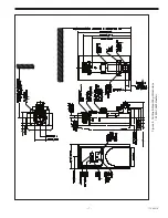
Page 17: ... 17 115 6031 0 Figure 4 Outline Mounting Dimensions 12 kW 15 kW Heaters ...
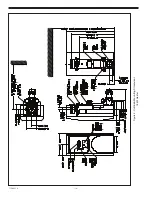
Page 18: ...115 6031 0 18 Figure 5 Outline Mounting Dimensions 18 kW Heater ...

