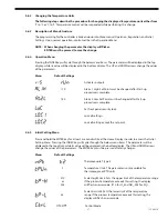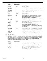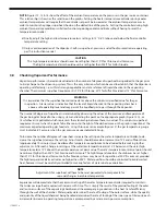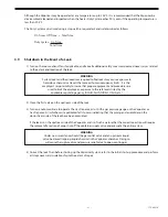
- 33 - 115.6031.0
4 MAINTENANCE
It is mandatory that the Vaporizer be shut down at least once a year for cleaning and inspection of the vaporizing
chamber. This requirement is based on the recommendation of the Chlorine Institute, Inc. for Chlorine service.
However, State and Local Regulatory Agencies should be consulted to make certain this recommendation conforms
to their minimum requirements. In all cases, it is recommended that the Vaporizer be disassembled, cleaned and
inspected when the heater Duty Cycle reaches 90%. This situation indicates a loss of evaporation ability possibly due
to deposit build-up in the evaporating chamber or the water jacket.
A preventative maintenance kit, P/N 22257, is available from the factory. The kit contains 2-Immersion Heater
Gaskets, 4-Magnesium Anodes, 4-Anode Grommets, 1-Chamber Gasket and a Service Record Tag.
The heater on/off cycle times may be determined using a stopwatch or equivalent and the heater Duty Cycle is
calculated as follows:
On Time + Off Time = Total Time
Duty Cycle = On Time
Total Time
The low water level switch should be checked for proper operation at least once a year by lowering the water level in
the Vaporizer. Be certain to turn on the make-up water and that the Vaporizer is operating normally after performing
this test.
NOTE
During disassembly and cleaning, inspect all parts thoroughly and replace any worn or damaged parts.
When a part which comes into contact with either the liquid or gaseous chemical needs replacement,
it is mandatory that the new part be made of materials which will withstand the corrosive action
of the chemical being handled.
Therefore, only De Nora Water Technologies parts, manufactured from materials selected for their
proper corrosion-resistant properties, must be used. When ordering parts, always furnish the
complete model and serial number of the Vaporizer, and the chemical being used.
Refer to Figure 3 and the exploded views shown in Section 6 to supplement the following text. Additionally, if the
Vaporizer is located indoors, turn on the exhaust fan and open the doors and windows to provide the maximum
ventilation possible. This is especially necessary during the steam cleaning portion of this procedure since the fumes
emitted from the non-volatile residue are noxious and may at times be nauseous.
1) Shut down the Vaporizer as described in Section 3.11.
2) Lift and remove front and back covers.
3) Remove eight screws and the reinforcing strip located at the back top edge of the cabinet.
4) Remove the four top panel screws and top panel attached to the side panels.
5) Remove four screws securing side panels to mounting brackets and remove side panels. (Two screws per panel.)
6) Disconnect the removable pipe section which interconnects the liquid chemical supply line to the Vaporizer
inlet connections.
CAUTION
Chlorine or Sulfur Dioxide will combine with water (even the moisture in air) to form a
very corrosive acid. When any piping section is opened or disconnected for servicing, the opening
must be sealed immediately. This also applies when changing chemical containers.
7)
Connect a supply of compressed air to the Vaporizer inlet connection, unlock and open the vent blow-off valve,
and turn on the air to purge the vaporizing chamber free of all residual vapors emitted from the accumulated
deposits of non-volatile residue. Then turn off and disconnect the air supply, close the vent blow-off valve,
and disconnect the removable pipe section which interconnects the Vaporizer outlet connection to the gas
discharge line.
Summary of Contents for Capital Controls 71V3B Series
Page 1: ... 1 115 6031 0 Instruction Manual Series 71V3B Electrically Heated Vaporizer CAPITAL CONTROLS ...
Page 9: ... 9 115 6031 0 Figure 1 Sectional Diagram ...
Page 17: ... 17 115 6031 0 Figure 4 Outline Mounting Dimensions 12 kW 15 kW Heaters ...
Page 18: ...115 6031 0 18 Figure 5 Outline Mounting Dimensions 18 kW Heater ...

