- 35 - 115.6031.0
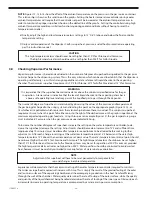
Be certain to orient the support flange so that the inlet and outlet connections of the vaporizing chamber are
located in their original position. However, do not reconnect the removable pipe sections at this point.
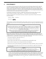
If the Vaporizer is equipped with cathodic protection, it is recommended that the magnesium rods be replaced
at this time.
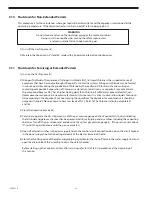
If the electric immersion heater was removed for cleaning, inspect the gasket prior to reassembly and replace the
gasket if necessary.
When replacing the heater gasket(s), torque the bolts with dry lubed threads evenly in a crisscross star pattern to
a torque of 30 Ft-lbs.
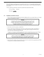
15) Fill the water chamber to operating level, restore power to the control circuits and heater, and bring the
Vaporizer up to operating temperature.
16) Reconnect the supply of dry compressed air or nitrogen to the Vaporizer inlet connection and turn on the air
to purge the vaporizing chamber of all moisture. Then turn off and disconnect the air supply. Reconnect the pipe
sections, being certain to install new gaskets in each of the joints.
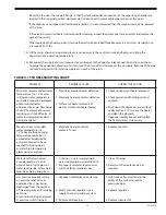
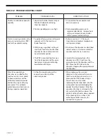
TABLE 4-1 TROUBLESHOOTING CHART
PROBLEM
PROBABLE CAUSE
CORRECTIVE ACTION
Minimum recommended water
temperature (i.e., 15°F below
setting on water temperature
controller) cannot be achieved
and/or maintained as
evidenced by: a) gas flow being
shut off by closure of pressure
reducing and shut-off valve, b)
water low temperature alarm
being energized.
1. Electric immersion heater defective.
2. Magnetic heater contactor defective.
3. Surfaces of heater elements of
electric immersion heater fouled.
1. Check continuity of heater elements.
2. Check operation of holding coil and
contacts.
3. Shut down the Vaporizer, as described
under Section 3.10, remove the heater
and clean the elements.
Upon reassembly inspect and replace
the heater gasket, if necessary.
Maximum recommended
water temperature (i.e.,
15°F above setting on water
temperature controller) is
exceeded as evidenced by:
a) water observed to have
reached its boiling point,
b) water high temperature
alarm being energized.
1. Magnetic heater contactor
contacts fused.
1. Replace contacts.
Water level below normal
as evidenced by: a) visual
observation of sight glass of
water level gauge, b) low water
level alarm being energized.
1. Y-strainer in water supply line to
water supply piping assembly dirty.
2. Improperly set water level control
switch or faulty solenoid valve.
1. Clean Y-strainer
2. Reset switch or replace valve, as
required.
Gas pressure exceeds setting
on pressure relief valve as
evidenced by: a) gas being
discharged from the terminus
of the emergency and servicing
vent line,
b) vent alarm being energized,
c) pressure switch tripped.
1. Vaporizer isolated by valve closure.
2. Faulty pressure regulator in air
supply line to air padding system.
3. Rupture disk leaking.
1. Open valve after ascertaining the
ability of the system to receive
pressurized gas.
2. Replace regulator.
3. Replace rupture disk.
Summary of Contents for Capital Controls 71V3B Series
Page 1: ... 1 115 6031 0 Instruction Manual Series 71V3B Electrically Heated Vaporizer CAPITAL CONTROLS ...
Page 9: ... 9 115 6031 0 Figure 1 Sectional Diagram ...
Page 17: ... 17 115 6031 0 Figure 4 Outline Mounting Dimensions 12 kW 15 kW Heaters ...
Page 18: ...115 6031 0 18 Figure 5 Outline Mounting Dimensions 18 kW Heater ...

