115.6031.0
- 4 -
4 MAINTENANCE ............................................................................................................................................................... 33
5
SULFUR DIOXIDE APPLICATIONS .................................................................................................................................. 40
Certificate of Conformity ............................................................................................................................................... 43
FIGURES
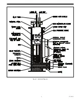
1
Sectional Diagram ....................................................................................................................................................................................... 9
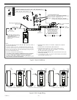
2
Typical Installation ....................................................................................................................................................................................16
3
Water Supply Piping .................................................................................................................................................................................16
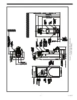
4
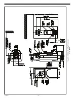
Outline & Mounting Dimensions, 12 kW & 15 kW Heaters .........................................................................................................17
5
Outline & Mounting Dimensions, 18 kW Heater ............................................................................................................................18
6
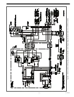
Interconnection & Wiring Diagrams for Vaporizers with Integral Magnetic Heater
Contactor and LOVE Controller ..........................................................................................................................................................19
7
Interconnection & Wiring Diagram for Vaporizers with Remote Magnetic Heater
Contactor and LOVE Controller ............................................................................................................................................................20
8
Interconnection & Wiring Diagram for Vaporizers with Integral Magnetic Heater
Contactor & Water Level Control and LOVE Controller ...............................................................................................................21
9
Typical Interconnection Wiring Diagrams for Vaporizers with Remote Magnetic
Heater Contactor & Water Level Control and LOVE Controller..................................................................................................22
10
Temperature Controller Controls & Indicators (LOVE Controller) ............................................................................................26
11
Controller Operation Label ....................................................................................................................................................................29
12
Chlorine: Temperature - Pressure Relationship ..............................................................................................................................37
13
Sulfur Dioxide: Temperature - Pressure Relationship ...................................................................................................................38
14
Ammonia: Temperature - Pressure Relationship ............................................................................................................................39
Summary of Contents for Capital Controls 71V3B Series
Page 1: ... 1 115 6031 0 Instruction Manual Series 71V3B Electrically Heated Vaporizer CAPITAL CONTROLS ...
Page 9: ... 9 115 6031 0 Figure 1 Sectional Diagram ...
Page 17: ... 17 115 6031 0 Figure 4 Outline Mounting Dimensions 12 kW 15 kW Heaters ...
Page 18: ...115 6031 0 18 Figure 5 Outline Mounting Dimensions 18 kW Heater ...


