3
1 . I N T R O D U C T I O N
2 . S A F E T Y I N S T R U C T I O N S
EN
3 . I N S TA L L AT I O N
4
.
Place the fuse holder for each positive cable within 40 cm from the positive terminal of the battery and connect one end of
the power cable to the holder after connecting the other end to the DSP unit. Do not install the fuse.
5
. Route all signal cables next to each other and separately from the power cables.
6
. Connect the wires of RCA input. The input signal power must be between 0.2
V - 6 V.
1.
Before installing the DSP unit disconnect the battery from the electrical system.
3.
Connect the power supply with the correct polarity. Connect (+) terminal of the DSP unit to the cables stretching from the
positive terminal of the battery and (-) terminals of the DSP unit – to the cables stretching from the negative terminal of the
battery.
2
.
To connect the DSP unit it is necessary to stretch the power cable from the location of the battery to the place of installation
of the DSP unit. Select the power cable with the appropriate regulations in AWG.
9. After installation is complete, check the wiring of the system and make sure that all connections have been made correctly.
Before installing the fuse, disconnect the positive lead from the battery and then install the fuse in the fuse holder. Using the light
bulb 12 V 21 W, connect the positive lead to one contact of the bulb and the other contact of the bulb to the positive terminal of
the battery.
11. LED indicator on front of the
DSP unit
turns green to indicate that the
DSP unit
is turned on.
8. Fasten the DSP unit properly when installing it in the vehicle. If the component is disconnected during driving, it may cause
serious damage to the passengers of the vehicle or another vehicle.
It is not recommended to screw the DSP unit directly to the
metal it can lead to distorsions at the signal outputs.
7. To connect the power wire supply is necessary to use special power cables.
10
.
To activate the DSP unit, it is necessary to apply the positive potential of 12 volts to the control input of the DSP (REM IN)
through a switch or a corresponding control output (REMOTE OUT) with the head unit (HU) or u
se the DSP power-on switch
labeled "TURN ON" to select the desired auto power-on mode.
W
hen properly connected, the bulb must briefly light up and go out. Now you may connect the positive lead to the (+) of the
battery. If the light does not go out, then something is wrong. This will prevent damage to the DSP unit in case of reverse polarity
and unwanted sparks when connecting.
To ensure proper use, please carefully read through this manual before using this product. It is especially important that you
read and observe caution’s in this manual. Please keep the manual in a safe and accessible place for future reference.
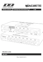
Thank you for purchasing this Deaf Bonce product of Machete series! Our company is committed to the creation of extremely
loud sound systems with no loss of quality.
2
.
Check the state of on-board power supply of your vehicle, the battery and the alternator. When the engine is running,
depending on the ambient temperature, the voltage to be outputted by the alternator must be within the range of 14 to 14.7 V.
Open circuit voltage (OCV) of the battery must be within the range of 12.5 to 13 V.
3
.
Do not place the DSP unit in the engine compartment and also in the places exposed to water, moisture, dust or dirt.
1. Make sure that your vehicle has a 12V DC electrical system with negative grounding. Before installing this DSP unit in cars,
trucks or buses, check the battery voltage.
4
.
Never stretch the cables outside of the car and near the moving parts of the car. This can lead to destruction of the
insulating layer, short circuit and fire.
5.
The DSP unit should be installed in areas of the car where the temperature varies from 0 °C (32 °F) to 55 °C (131 °F). The DSP
unit should be in a place with a good air circulation. The horizontal position of the DSP unit is the best way to install.
1
3.
To avoid accidental damage, keep the DSP unit in its original packaging prior to installation.
8
.
Make sure that the location of the DSP unit does not violate the proper operation of mechanical and electrical devices of
the vehicle.
1
0.
When performing plumbing, drilling or cutting works with the car, make sure that there is no wiring, brake lines, fuel pipe
or other structural elements under the place of work. Follow the safety rules! Use protective glasses and gloves.
9
. Make sure that during the installation and connection of the battery, the power cables are not shorted.
1
1. To protect the wires use rubber gaskets if the wire passes through a hole in the plate, or other similar materials if it lies
close to the parts exposed to heat.
6
.
During the operation the DSP unit may be heated up to 80 °C (176 °F). Before you touch it, make sure it is not overheated
that may be dangerous.
1
2.
Make sure that all the cables are fixed over the entire length. Also make sure that their outer protective shell is non-
combustible. Use a clamping screw to secure the positive and negative cables next to the appropriate terminals of the DSP unit.
7
.
To improve the cooling of the DSP unit, it is recommended to clean periodically the heatsink from dust. When cleaning the
heatsink strong solvents should not be used as they may damage the DSP unit. Do not use compressed air, because solids can
penetrate inside the DSP unit. Cleanings best done with wet towels or cloth.
1
4. Use high-quality copper RCA, speaker and power cables.
Summary of Contents for Machete series
Page 1: ...Machete series M8 DSP http alphard audio DSP ...
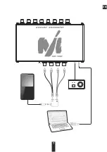
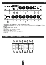
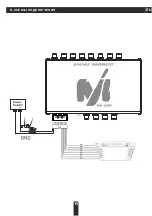
Page 6: ...6 WIRING DIAGRAMS 6 EN ...
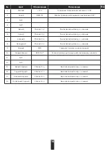
Page 7: ...7 EN ...
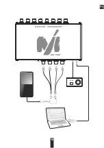
Page 8: ...8 EN ...
Page 14: ...RU 6 СХЕМЫ ПОДКЛЮЧЕНИЯ 15 ...
Page 16: ...RU 16 ...
Page 17: ...RU 17 ...
Page 20: ...http alphard audio ...

