162
STAGE 41
STAGE 41
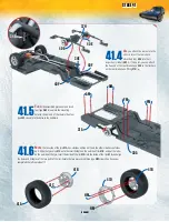
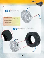
41.1
G
et
the chassis and very
carefully put it upside down on
your work surface. Find the end
of the gear box and insert the linchpin on the
front coupling
35C
(i.e. the coupling with the
smallest diameter), as shown in the
illustration.
41.2
I
nsert
the two rear shock absorber cylinders
40F
into the
holes indicated in the illustration, then secure with two type
AM
screws. Insert a spring
40G
into each of the two shock
absorber cylinders
40F
.
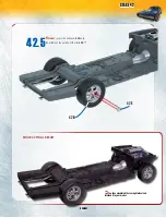
41.3
t
ake
the rear axle complete
with the leaf springs. Align the
ends of the leaf springs with the
chassis: the two rear reinforcement plates
38F
and
39F
go above the holes in the rear section of the
chassis
31A
, while the front reinforcement
plates
38C
and
39C
line up with the holes in the
middle section of the chassis
30A
. Insert the
linchpin on the rear coupling
35D
into the
corresponding hole in the rear differential
36B
.
Attention: you will also have to deal with the shock
absorbers in this assembly session, as illustrated in the
next step.
35C
12C
12D
39F
39C
38F
38C
36B
30A
35D
31A
40G
40F
31A
40F
40G
AM
AM
Summary of Contents for MODEL SPACE FAST & FURIOUS DODGE CHARGER R/T
Page 1: ...11 11 pack pack ...


