background image

Troubleshooting

39

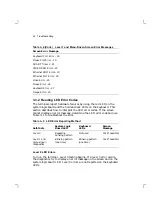
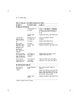
Table 3–1 (Cont.)

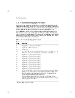
Troubleshooting by Error Code

Error
Code

Solution

3

25

Replace the system logic board (4.6).

26

Run the Mouse Port Test with external loopback, using the Diagnostics
dialog box (2.1.2). If the same error occurs, replace the system logic
board (4.6). Otherwise, replace the mouse (4.9).

27

Replace the keyboard (4.9). If the same error occurs, replace the
system logic board (4.6).

28

Turn the system box’s power switch off and on. If the same error
occurs, replace the system logic board (4.6).

29

Replace the system logic board (4.6).

31

Replace the system logic board (4.6).

32

Check and adjust the setting of the monitor selection switch (1.1.2).
Then turn the system box’s power switch off and on. If the same error
occurs, replace the system logic board (4.6).

33

Replace the system logic board (4.6).

34

Replace the system logic board (4.6).

43

Replace the image board (4.3).

3

Section numbers follow the solution.

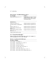
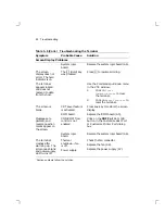
Table 3–2

Troubleshooting Error Code 13

Error Message

Solution

3

MAIN Memory Error - 13

Replace the system logic board (4.6).

Optional RAM Simm 1 Error - 13

Replace SIMM card 1 (4.4). Turn the
system box’s power switch on. If the
same error occurs, replace the RAM
controller board (4.2).

Optional RAM Simm 2 Error - 13

Replace SIMM card 2 (4.4). Turn the
system box’s power switch on. If the
same error occurs, replace the RAM
controller board (4.2).

3

Section numbers follow the solution.

Summary of Contents for DECimage 1200

Page 1: ...VT1000 VT1200 and DECimage 1200 Service Guide Order Number EK V1000 SV 002 Digital Equipment Corporation...

Page 2: ...not supplied by Digital Equipment Corporation or its affiliated companies Restricted Rights Use duplication or disclosure by the U S Government is subject to restrictions as set forth in subparagraph...

Page 3: ...ls 7 1 2 3 Customizing the Terminal 8 1 2 4 Overriding Passwords 8 1 3 Site Requirements 8 2 Testing 2 1 Terminal Self Tests 10 2 1 1 Successful Power Up Self Tests 11 2 1 2 Menu Driven Diagnostic Tes...

Page 4: ...M Controller Board VT1000 VT1200 Only 52 4 3 Image Board DECimage 1200 Only 53 4 4 SIMM Cards 54 4 5 ROM Board 56 4 6 System Logic Board 57 4 7 Power Supply 59 4 8 Fan 60 4 9 Keyboard Mouse and Printe...

Page 5: ...ests 13 2 3 Diagnostics Dialog Box Buttons 19 2 4 NCP Tests 23 2 5 P3 Values to Specify Mode Bits 24 3 1 Troubleshooting by Error Code 38 3 2 Troubleshooting Error Code 13 39 3 3 Level 0 Screen Error...

Page 6: ......

Page 7: ...er Services Engineers and qualified self maintenance customers Organization The guide has five chapters that cover the following topics Terminal overview Testing the terminal Troubleshooting the termi...

Page 8: ...onventions are used in this guide Convention Meaning terminal Refers to the VT1000 terminal the VT1200 terminal and the DECimage 1200 terminal mouse Refers to any pointing device such as a mouse a puc...

Page 9: ...like a traditional terminal Display multiple video terminal VTE windows and applications over both the Ethernet and serial lines at the same time Interact over an Ethernet network with multiple VTE wi...

Page 10: ...ption Monitor VR150 VR262 VR315 VR319 or VRE01 electroluminescent EL flat panel System board LED Red LED visible through the ventilation slots on the side of the system box Terminal logo VT1000 VT1200...

Page 11: ...conceal the connectors and cables VT1000 and VT1200 System Box FRUs The system box contains the following field replaceable units FRUs Part numbers follow each FRU Appendix B lists all part numbers 2...

Page 12: ...ts FRUs Part numbers follow each FRU Appendix B lists all part numbers 1 2 3 4 5 6 M A 0 5 1 0 9 0 D G 6 5 4 3 2 1 System logic board 54 19783 01 SIMM card installed on the other side of the image boa...

Page 13: ...or image board SIMM stands for single in line memory module The controller board has slots for three 1 megabyte SIMM cards System Box Connectors and Switches The following figure shows the connector...

Page 14: ...tem box is set to match the monitor To find the monitor s model number check the labels on the rear of the monitor NOTE The terminal searches for the monitor selection switch position only during the...

Page 15: ...on host computers Video Terminal Session The terminal has a video terminal VTE window that lets you log into a host as you would on a conventional video terminal The terminal s VTE window works like...

Page 16: ...font path group code and specific addresses in use Section 5 1 1 2 4 Overriding Passwords Performing a Secure Reset allows you to override saved passwords You may need to perform a secure reset if a u...

Page 17: ...s a traditional video terminal System Software Support The following table summarizes the system resources needed to open X window sessions or video terminal VTE sessions Operation Operating System Co...

Page 18: ...ies of self tests to help you isolate failures to faulty field replaceable units FRUs You can run self tests in three ways Automatically during power up Using menu driven diagnostics Using remote diag...

Page 19: ...m running Level 0 Testing When you turn on the terminal level 0 testing begins When level 0 testing completes successfully within 5 seconds the operating system starts and level 1 testing begins autom...

Page 20: ...by the Terminal Manager window Figure 2 1 The Terminal Manager title bar displayed on your terminal indicates the software version running The diagnostic summary box in the window contains the message...

Page 21: ...inter port test Keyboard test Image test if installed System Logic Board LED Power Up Sequence When the terminal powers up the red LED on the system logic board turns on At the start of level 0 testin...

Page 22: ...ons cause a software reset and write messages on the screen Loopback Connectors The loopback test can check the driver and receiver hardware of the following ports on the rear of the system box Port L...

Page 23: ...x Use the following procedure to display the Diagnostics dialog box and choose tests NOTE Running the menu driven diagnostic tests resets the terminal and quits all session activity 1 Turn on the term...

Page 24: ...All White Session MA 0762 90 DG NOTE If the user has chosen the left handed settings for the mouse MB1 is the button on the right 5 Release the Shift and Ctrl keys 6 Move the mouse pointer down to th...

Page 25: ...Testing 17 NOTE The Image Hardware Test is only listed in the dialog box for a DECimage 1200 terminal MA 0512 90 RAGS...

Page 26: ...est Click on the Perform External Loopback on Port Tests button Click on either the Run Selected Tests button or Run All Tests button If the test s run successfully The following message appears in th...

Page 27: ...ge Hardware Test Firmware verifies the image board functions The image board and the image ROM board must be installed to run this test Host Port Test Verifies the internal data paths of the host port...

Page 28: ...all tests once with or without external loopbacks 2 1 3 Displaying Video Alignment Patterns The terminal can display the following video alignment patterns for adjusting the monitor display Screen of...

Page 29: ...al remotely from any host system that supports the MOP version 3 0 console carrier protocol VMS host software that implements the console carrier protocol includes Network control protocol NCP Local a...

Page 30: ...rmat is CONNECT VIA circuit id PHYSICAL ADDRESS terminal s_Ethernet_address For example NCP CONNECT VIA bna 0 PHYSICAL ADDRESS 08 00 00 34 00 7D To determine the circuit id use the following command N...

Page 31: ...y a range of tests P1 P2 P3 Specifies one or more mode bits to control execution of the self test modules Table 2 5 Table 2 4 NCP Tests Test Number Description 0 ROM checksum test 1 NVR checksum test...

Page 32: ...Examples NOTE NCP may time out while waiting for the terminal to perform self tests The timeout period of NCP version Phase V is adjustable To run test number 5 with mode bits 4 and 1 specified 1 Calc...

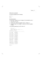
Page 33: ...ensure the terminal operates correctly In the following example the error code is 13 Testing Test 16 Failed Optional RAM Simm 2 Error 13 DIAGNOSTIC MAILBOX test_type 00FFFF8E test_mode 00000000 test_r...

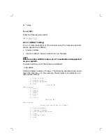
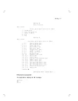
Page 34: ...nd supported on your system To enable LANSA enter the following command RUN LANSA LANSA displays a series of menus The following example shows how to reach the test menu In the example the terminal to...

Page 35: ...t test 6 T 5 Printer port test 7 T 6 DUART 2 channel a 8 T 7 Mouse port test 9 T 8 Keyboard test 10 T 9 Ethernet port test 11 T 10 Mouse test 12 T 11 Video Test 13 T 12 Ethernet ROM checksum test 14 T...

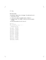
Page 36: ...ly In the following example the error code is 13 Testing Test 16 Failed Optional RAM Simm 2 Error 13 DIAGNOSTIC MAILBOX test_type 00200000 test_mode 00000000 test_result 00200000 error_ext0 00800000 e...

Page 37: ...ble LATCP on a VMS system enter one of the following commands MCR LATCP or RUN SYS SYSTEM LATCP The application displays the LCP prompt Examples The following command shows the server characteristics...

Page 38: ...d Remote Service Name X SERVER Actual Remote Node Name LAT_08002B11D26E Link Name LAT LINK Local Port Name LTA12 application Specified Remote Node Name LAT_08002B11D26E Specified Remote Service Name X...

Page 39: ...0 window probes sent 0 packets sent with URG only 0 window update only packets sent 0 control SYN FIN RST packets sent 5 total packets received 1 packets received in sequence 4 bytes received in sequ...

Page 40: ...tes received 249828 Multicast packets received 0 Overflow errors 249905 Tot packets received 1 Packets lost no system resources 0 Packets lost no user resources 0 Unrecognized destination on rcv 0 Bab...

Page 41: ...ts for memory delayed 0 calls to protocol drain routines END 2 4 2 Using ping You can use the UNIX ping command to verify the network hardware Internet protocol IP and ICMP layers Tracking a single po...

Page 42: ...atistical information r Bypass the normal routing tables and send directly to a host on an attached network If the host is not on a directly attached network an error is returned You can use this opti...

Page 43: ...e of general problems 3 1 Identifying the Terminal s Configuration You can identify the terminal s hardware configuration by checking the firmware revision level To identify this terminal Check the ti...

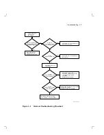
Page 44: ...gic board LED turns on and off To see the LED look through the ventilation slits on the side of the system box Section 1 1 The monitor displays a pie graph representing the progress of the self tests...

Page 45: ...menu driven diagnostics with loopbacks installed Check the monitor s video cable Determine LED error code Use Table 3 1 to troubleshoot Does an error message appear on the screen Is the monitor s LED...

Page 46: ...logic board 4 6 12 Replace the ROM board 4 5 13 See Table 3 2 14 Run the NVR Checksum Test from the Diagnostics dialog box 2 1 2 If the same error occurs replace the system logic board 4 6 15 Replace...

Page 47: ...eck and adjust the setting of the monitor selection switch 1 1 2 Then turn the system box s power switch off and on If the same error occurs replace the system logic board 4 6 33 Replace the system lo...

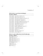
Page 48: ...the system logic board 4 6 System Memory Refresh or address decode error 13 Replace the system logic board 4 6 3Section numbers follow the solution 3 3 1 Screen Error Messages Tables 3 3 and 3 4 list...

Page 49: ...ation Occurrence 28 LEVEL0 ERROR Illegal OPCODE Occurrence 28 LEVEL0 ERROR No display interrupt error 28 LEVEL0 ERROR Perpetual pending Display Interrupt 28 LEVEL0 ERROR Trap Interrupt Occurrence 28 L...

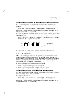
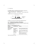
Page 50: ...ribes how to interpret the LED error codes If the screen cannot display an error message determine the LED error code and use Table 3 1 to troubleshoot the error Table 3 5 LED Error Reporting Method S...

Page 51: ...utions Level 1 LED Error Codes After level 0 testing is complete the operating system starts and level 1 testing starts When a level 1 error occurs the screen displays an error message in the upper le...

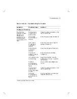
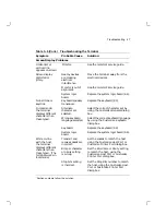
Page 52: ...ooting General Problems Table 3 6 describes some general operating problems with possible causes and suggested solutions Table 3 6 Troubleshooting the Terminal Symptom Probable Cause Solution3 Monitor...

Page 53: ...Enter the host name or host IP address Chapter 5 Font paths are incorrect or missing Enter the font paths Chapter 5 Terminal IP address is wrong or missing Enter the terminal address Chapter 5 LAT sli...

Page 54: ...ence Keyboard System logic board Replace the keyboard 4 9 Replace the system logic board 4 6 DECimage 1200 The power up test fails and the pie graph is distorted The incorrect ROM board is installed R...

Page 55: ...age selected Select the correct character set by using the Customize General dialog box Select the correct keyboard language by using the Customize Keyboard dialog box Keyboard Replace the keyboard 4...

Page 56: ...on Reset Terminal to reset the terminal The screen is blank CRT saver feature is activated Press any key to restore the screen display ROM board Replace the ROM board 4 5 Messages are garbled and reve...

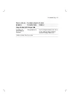
Page 57: ...inal Symptom Probable Cause Solution3 Image Problems DECimage 1200 No image or a partial image is displayed Image board error Run the image hardware test 2 1 2 If the image hardware test fails replace...

Page 58: ...246 00 when handling any internal components This guide does not cover the FRUs for the VR150 VR262 VR315 VR319 and VRE01 monitors For information on the monitors see the following guides Monitor Docu...

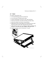
Page 59: ...ble from the rear of the monitor 5 Remove the monitor from the top of the system box 6 Release the top cover of the system box by pressing in the two push tabs on the side of the box with the power sw...

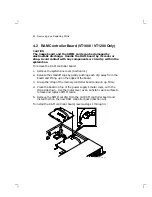
Page 60: ...e the standoff clips by gently pushing each clip away from the board and lifting up on the edges of the board 3 Grasp the strap of the memory controller board and pull up firmly 4 Place the board on t...

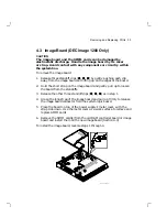
Page 61: ...board and gently pull up to loosen the board from the standoffs 3 Release the other three standoff clips as in step 1 4 Grasp the long strap of the image board and pull up firmly to release the image...

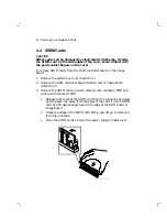
Page 62: ...e RAM controller board Section 4 2 or image board Section 4 3 3 Remove the SIMM cards in order starting with connector 4MB and ending with connector 2MB Release both sides of the SIMM card from the co...

Page 63: ...the second SIMM in 3MB and the last SIMM in 4MB Insert the SIMM card into the connector at a 45 degree angle Face the components on the SIMM card toward the components on the memory controller board o...

Page 64: ...rap 1 Remove the system box cover Section 4 1 2 Release the standoff clips by gently pushing each clip away from the board and lifting up on the edges of the board 3 Grasp the strap of the ROM board a...

Page 65: ...sure the user has a record of the customized settings Section 5 1 You will reenter required settings after installing the new system logic board To remove the system logic board 1 Remove the system bo...

Page 66: ...Ethernet and monitor connectors some force is needed to install the logic board Press the board firmly against the connector side of the enclosure and insert a screw into the center hole of the board...

Page 67: ...m logic board 3 Loosen the two screws holding the power supply to the system box 4 Lift up the screw side of the power supply to slide the power supply s holding tabs out of the slots on the bottom of...

Page 68: ...e the power supply Section 4 7 3 Disconnect the fan s power wire from the power supply as shown There are two fan connectors With the fan facing toward you the power wire is on the right 4 Slide the f...

Page 69: ...connect the keyboard mouse or printer from the rear of the system box You do not have to turn off the power G S F _ 1 6 8 9 _ 8 9 D G 5 2 1 2 3 4 5 6 To install a keyboard mouse or printer connect its...

Page 70: ...ng diagrams see the Getting Started chapter in the terminal s Installing and Using guide The chapter also describes how to override passwords using the secure reset feature 5 1 Before You Start Requir...

Page 71: ...hile holding down the button move the pointer down to the LAT menu item Release the mouse button The Customize LAT dialog box appears NOTE If you accidentally choose another menu item dismiss the new...

Page 72: ...for 30 seconds every 2 1 2 minutes If the wait is too long your system manager may be able to increase the host s multicast message frequency 6 Save the group code s and font path so you do not have t...

Page 73: ...host The host name is highlighted and appears in the text entry field at the bottom of the window Click on the Add button The host name is added to the Preferred Services scroll box Only add hosts you...

Page 74: ...minal Manager window pull down the Customize menu and choose the TCP IP menu item Move the mouse until the arrow shaped pointer is on the Customize menu name in the Terminal Manager s menu bar Press c...

Page 75: ...wait several minutes before the Set font path succeeded message appears 7 Save the terminal s IP address and the font path s so you do not have to enter them each time you turn on the terminal Pull d...

Page 76: ...ne or Korn shell DISPLAY your_terminal s_IP_address 0 export DISPLAY Begin an X window application by entering the appropriate command For example the following command starts a DECterm application dx...

Page 77: ...nal After the power up self tests are complete the Terminal Manager window appears 2 Press and hold down the Shift and Ctrl keys on the keyboard 3 With your other hand move the mouse until the pointer...

Page 78: ...15 90 RAGS 8 Click on the Yes button The terminal resets all settings to the factory default overriding the security and pause passwords Secure reset also increases the Secure Reset Count by one The s...

Page 79: ...DECimage 1200 Only To display the Customize Image dialog box choose the Image menu item from the Terminal Manager s Customize menu 1 Point to the Customize menu name in the Terminal Manager s menu ba...

Page 80: ...72 Starting a Session 2 Drag the pointer down to the Image menu item Release MB1 to display the Customize Image dialog box LJ 00044 RAGS...

Page 81: ...the VT1200 Video Terminal EK V1200 UG Installing and Using the DECimage 1200 Video Terminal EK V120I IN VT1000 Illustrated Parts Breakdown EK V1000 IP DECimage 1200 Illustrated Parts Breakdown EK D120...

Page 82: ...tic 74 39208 01 Dress panel plastic 74 39906 01 Fan 70 26582 01 Front bezel plastic VT1000 74 39210 01 Front bezel plastic VT1200 74 39210 02 Monitor selection switch knob 74 39905 01 Power supply ass...

Page 83: ...54 19803 03 Screw for power supply and system logic board 90 09984 07 SIMM card VX10X MD System logic board 54 19783 01 Standoff nylon unkeyed 12 19857 01 Standoff nylon keyed 12 19857 05 Top enclosu...

Page 84: ...Belgium Finland France Germany Netherlands Norway Portugal Spain Sweden BN19C 2E Canada BN19P 1K Denmark Israel BN19K 2E Ireland United Kingdom BN19A 2E Italy BN19M 2E Switzerland BN19E 2E USA 17 0060...

Page 85: ...French LK401 AC LK402 AC Denmark LK401 AD LK402 AD Finland LK401 AF LK402 AF France LK401 AP LK402 AP Germany Austria LK401 AG LK402 AG Hebrew LK401 AT None Italy LK401 AI LK402 AI Netherlands LK401...

Page 86: ......

Reviews: