2
Technical Description
This chapter provides a technical description of the following major sections of
the DEClaser 5100 printer:
•
Section 2.1 describes the block diagram, operational modes, low-voltage
power supply assembly (LVPSA) and interlock systems, and presents board
and connector level wiring diagrams.
•
Section 2.2 describes the paper feeding system plus paper size sensing and
detection.
•
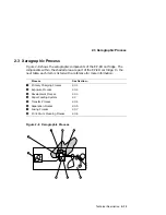
Section 2.3 describes the xerographic process.
•
Sections 2.4 and 2.5 present a detailed description of the scanner and
high-voltage power supply assembly (HVPSA).
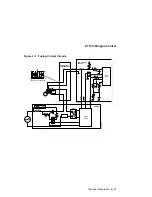
See the detailed wiring diagrams in Figures 6–2 through 6–5.
Technical Description 2–1
Summary of Contents for DEClaser 5100
Page 10: ......
Page 13: ...DSG 000172 Notes 1 ...
Page 14: ......
Page 61: ...2 5 HVPSA Figure 2 12 EP ED Cartridge DSG 000612 2 1 3 4 5 6 7 Technical Description 2 25 ...
Page 62: ...2 5 HVPSA DSG 000172 Notes 2 26 Technical Description ...
Page 70: ...3 2 Control Panel Operation DSG 000172 Notes 3 8 Operating the Control Panel ...
Page 90: ......
Page 124: ...7 5 Phantom Jams DSG 000172 Notes 7 8 FIPs for Fixing Paper Jams ...
Page 167: ...9 12 Board DC Control 1 2 4 5 7 8 9 6 3 10 DSG 000657 Removing and Replacing FRUs 9 31 ...
Page 224: ...10 1 Field Replaceable Units DSG 000172 Notes 10 4 FRU Part Numbers ...
Page 254: ...B 4 Connecting to OpenVMS VAX or ULTRIX Systems DSG 000172 Notes B 10 General Information ...
Page 264: ...D 3 Tools DSG 000172 Notes D 4 Training Documentation and Tools ...
Page 274: ......


