2.4 Scanner
2.4 Scanner
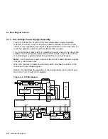
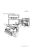
Figure 2–10 shows the circuits and components within the scanner assembly.
When the printer is powered on, the DC control board generates the scanner
clock (
SCNCLK
) signal that regulates the speed of the scanner motor. The
scanner motor does not run until a print command is received.
When
V SY NC
is received, the DC control board asserts the following signals
to turn on the scanner and laser:
•
SCANON
to run the scanner motor
•
ENBL
to enable the laser diode
•
LON
to force the laser diode on
When the scanner motor is up-to-speed, the scanner ready (
SCNRDY
) signal
is sent to the DC control board. The following conditions cause a scanner
motor error:
•
SCNRDY
fails to assert within 20 seconds of
SCON
.
•
SCNRDY
negates (goes high) for longer then 2.5 seconds while the
scanner motor is running.
When the scanning beam passes the beam detect (BD) mirror, it reflects the
light into the beam detector, creating the
BDI
signal. The DC control board
receives
BDI
and sends
BD
to the video controller board.
In response to
BD
, the video controller transmits the video data out (
V DO
)
signal to the DC control board, which sends it to the laser driver as the
V DAT A
signal.
The automatic power control (APC) regulates controls the intensity of the laser
light.
To start the laser the DC control board first asserts the
LON
signal, then
incrementally increases the value of the APC output (
AP COUT
) signal. This
action slowly turns the laser on.
When the laser is on, a portion of the laser light strikes the adjacent photodiode
and creates the APC input (
AP CIN
) signal.
AP CIN
feeds back to the DC
control board, which uses it to control
AP COUT
and thus stabilize the
intensity of the laser beam.
2–20 Technical Description
Summary of Contents for DEClaser 5100
Page 10: ......
Page 13: ...DSG 000172 Notes 1 ...
Page 14: ......
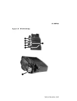
Page 61: ...2 5 HVPSA Figure 2 12 EP ED Cartridge DSG 000612 2 1 3 4 5 6 7 Technical Description 2 25 ...
Page 62: ...2 5 HVPSA DSG 000172 Notes 2 26 Technical Description ...
Page 70: ...3 2 Control Panel Operation DSG 000172 Notes 3 8 Operating the Control Panel ...
Page 90: ......
Page 124: ...7 5 Phantom Jams DSG 000172 Notes 7 8 FIPs for Fixing Paper Jams ...
Page 167: ...9 12 Board DC Control 1 2 4 5 7 8 9 6 3 10 DSG 000657 Removing and Replacing FRUs 9 31 ...
Page 224: ...10 1 Field Replaceable Units DSG 000172 Notes 10 4 FRU Part Numbers ...
Page 254: ...B 4 Connecting to OpenVMS VAX or ULTRIX Systems DSG 000172 Notes B 10 General Information ...
Page 264: ...D 3 Tools DSG 000172 Notes D 4 Training Documentation and Tools ...
Page 274: ......

