

Lit. No. TS-218B-0499
Therma-Stor Products
A Division of DEC International
Box 8050 Madison, WI 53708
Toll Free 1-800-533-7533
Local 1-608-222-5301
PHOENIX 300 Operation & Service Instructions
Table of Contents
1.
Specifications
................................................... 1
2.
Operation
.......................................................... 1
2.1 Transporting the Phoenix 300 ...................... 1
2.2 Location ........................................................ 1
2.3 Electrical Requirements ............................... 2
2.4 Condensate Removal ................................... 2
2.5 Ducting ......................................................... 2
2.6 Power Switch ................................................ 2
2.7 Pump Purge Switch ...................................... 2
2.8 Pump Fail Light............................................. 2
2.9 Hour Meter.................................................... 2
2.10 Defrost Control Adjustment ......................... 2
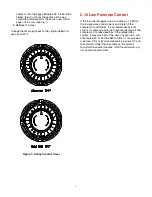
2.11 Low Pressure Control .................................. 3
3.
Maintenance
..................................................... 3
3.1 Air Filter ........................................................ 3
3.2 Blower Oiling ................................................ 3
3.3 Storage ......................................................... 3
4.
Service
.............................................................. 4
4.1 Warranty....................................................... 4
4.2 Technical description.................................... 4
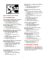
4.3 Troubleshooting............................................ 4
4.4 Refrigerant Charging .................................... 5
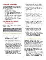
4.5 Blower Replacement .................................... 5
4.6 Compressor/Capacitor Replacement ........... 5
4.6A Checking Compressor Motor Circuits ..... 5
4.6B Replacing a Burned Out Compressor ..... 6
4.6C Replacing a Compressor- Non-Burn Out ... 7
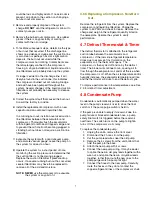
4.7 Defrost Thermostat & Timer......................... 7
4.8 Condensate Pump........................................ 7
4.9 Relay............................................................. 7
4.10 Time Delay .................................................. 7
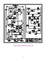
5.
Wiring Diagram
................................................. 8
6.
Service Parts List
............................................. 9
Serial No. ________________________________
Purchase Date ____________________________
Dealer's Name ____________________________
Read the operation and maintenance instructions
carefully
before
using this unit. Proper adherence to
these instructions is essential to obtain maximum
benefit from your Phoenix 300 dehumidifier.
1 Specifications
Model: PHOENIX 300 Dehumidifier
Electrical: 110-120 Vac, 12 Amps, grounded
Capacity: 176 pints per day @ 80
°
F, 60% RH
Operating Temp. Range: 33
°
F min., 105
°
F max.
Air Flow: 540 CFM without external ducting
Refrigerant Charge: 2 lbs., 5 oz. R-22
Optional Duct connection: 10" round outlet
Size: 45" high x 24" wide x 20" deep cabinet
46" high x 29" wide x 25" deep overall
Weight: 175 lbs.
2 Operation
2.1 Transporting the Phoenix
The Phoenix 300 must always be upright when
transported by vehicle. It may be tipped on to its handle
and back for loading and moving by hand.
2.2 Location
Note the following precautions when locating the
Phoenix 300:
•
It is designed to be used
INDOORS ONLY
.
•
If used in a wet area, plug it into a
GROUND FAULT
INTERRUPTER.
••••
DO NOT
use the Phoenix 300 as a bench or table.
•
It must always be used in the upright position.
•
The air inlet on top & the side outlet must be at least
1 foot from walls and other obstructions to air flow.
•
If the humid area is very large, dehumidification can
be improved by adding an outlet duct to circulate air
to stagnant areas (see Sec. 2.5).


