background image

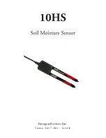
10HS

5

CONNECTING SENSORS

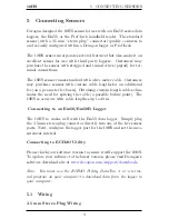
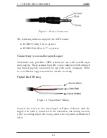
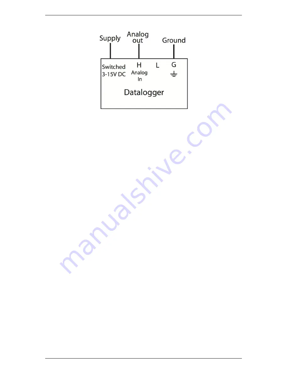
Figure 3: Pigtail End Wiring to Data Logger

Note: The acceptable range of excitation voltages is from 3 to 15
VDC. If you wish to read your Decagon sensor with the Campbell
Scientific Data Loggers, you will need to power the sensors off of the
switched 12 V port.

If your 10HS is equipped with the standard 3.5 mm plug and you
want to connect it to a non-Decagon data logger, you have two op-
tions. First, you can clip off the plug on the sensor cable, strip and
tin the wires, and wire it directly into the data logger. This has
the advantage of creating a direct connection with no chance of the
sensor becoming unplugged; however, it cannot be easily used in the
future with a Decagon readout unit or data logger.

The other option is to obtain an adapter cable from Decagon. The
3-wire sensor adapter cable has a connector for the sensor jack on
one end, and three wires on the other end for connection to a data
logger (this type of wire is often referred to as a “pigtail adapter”).
Both the stripped and tinned adapter cable wires have the same ter-
mination as seen above; the white wire is excitation, red is output,
and the bare wire is ground.

11

Summary of Contents for 10HS

Page 1: ...Decagon Devices Inc Version July 7 2016 14 04 38...

Page 2: ...es Inc 2365 NE Hopkins Court Pullman WA 99163 Phone 509 332 5600 Fax 509 332 5158 Website www decagon com Email support decagon com or sales decagon com Trademarks c 2007 2013 Decagon Devices Inc All...

Page 3: ...bout the 10HS 3 2 1 Background Info 3 2 2 Specifications 4 3 Theory 5 4 Installing the Sensor 6 4 1 Procedure 6 5 Connecting Sensors 9 5 1 Wiring 9 6 Calibration 12 6 1 Dielectric calibration 12 6 2 M...

Page 4: ...through Friday between 8am and 5pm Pacific time Note If you purchased your sensor through a distributor please con tact them for assistance Email support decagon com or sales decagon com Phone 509 332...

Page 5: ...its manufacturer Seller shall not be liable to Buyer for loss damage or injuries to persons including death or to property or things of whatsoever kind including but not without limitation loss of ant...

Page 6: ...re sensor The new 10HS sensor uses the same 70 MHz oscillator frequency as the EC 5 but has a larger soil volume and requires no special calibration when you use it with other systems The 10HS has two...

Page 7: ...08 VWC in mineral soils from 0 to 0 50 m3 m3 0 to 50 VWC Measurement Time 10 ms milliseconds Power Requirements 3 VDC 12 mA to 15 VDC 15 mA Output 300 to 1 250 mV independent of excitation voltage Ope...

Page 8: ...t time t Vi is the starting voltage and Vf is the applied or supply voltage Further for a capacitor with a geometrical factor of F the capacitance is related to the dielectric permittivity of the medi...

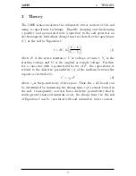
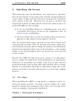
Page 9: ...kes This can attenuate the senors electromag netic field and adversely affect readings In addition the 10HS sensor should not be installed within 5 cm of the soil surface or the sensing volume of the...

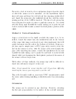
Page 10: ...any other implement that will guide the sensor into the soil at the bottom of the hole Many peo ple have used a simple piece of PVC pipe with a notch cut in the end for the sensor to sit in with the...

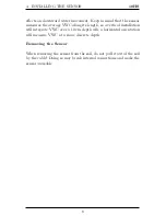
Page 11: ...its length so a vertical installation will integrate VWC over a 10 cm depth wile a horizontal orientation will measure VWC at a more discrete depth Removing the Sensor When removing the sensor from t...

Page 12: ...ional fee on a per meter fee basis Obtaining custom length cables elim inates the need for splicing the cable a possible failure point The 10HS is accurate with cable lengthes up to 40 m Connecting to...

Page 13: ...Decagon data loggers These sensors typically come configured with stripped and tinned pigtail lead wires for use with screw terminals Refer to your distinct logger manual for details on wiring Pigtai...

Page 14: ...d tin the wires and wire it directly into the data logger This has the advantage of creating a direct connection with no chance of the sensor becoming unplugged however it cannot be easily used in the...

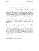
Page 15: ...5 V DC a 2 589 x 10 10 mV 4 x 5 010 x 10 7 mV 3 3 523 x 10 4 mV 2 9 135 x 10 2 mV 7 457 4 6 2 Mineral Soil Calibration For convenience Decagon has also developed a standard calibration equation for mi...

Page 16: ...oil type With a soil specific calibration the accuracy of the VWC measurements will be improved to 1 to 2 in any soil or other porous medium If you are interested in a soil specific calibration for yo...

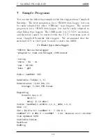
Page 17: ...the 2 5 V excitation port of many Campbell Scientific data loggers We recommend that the switched 12 V or CAO port be used to excite the 10HS Cr Basic type data logger CR1000 Series Datalogger progra...

Page 18: ...10HS bare gnd G or AG Table 1 Program 01 10 Execution Interval seconds set C1 high to pull SW 12 port high 1 Do P86 1 41 Set Port 1 High delay program 10 ms and measure SE channel 1 in units of volts...

Page 19: ...9 C1 6 7 37 C2 7 2 97 C3 8 0 0 C4 9 0 0 C5 5 If time is P92 1 0000 Minutes Seconds into a 2 60 Interval same units as above 3 10 Set Output Flag High Flag 0 6 Real Time P77 18390 1 1110 Year Day Hour...

Page 20: ...63 USA Type of Equipment Dielectric Soil Moisture Sensor Model Number 10HS Year of First Manufacture 2008 This is to certify that the 10HS dielectric soil moisture sensor man ufactured by Decagon Devi...

Page 21: ...ll Scientific 4 Communications 11 Compatibility 4 Decagon 4 Non Decagon 10 Other 4 Dielectric Permittivity 12 ECH2O Utility 10 14 Email 1 Installation Horizontal 6 Vertical 7 Measurement Time 4 Minera...

Reviews: