Sp
eedSp
y™
U
ser
’s & I
nstalla
tion M
anual
10
3.4 Interconnect Functions
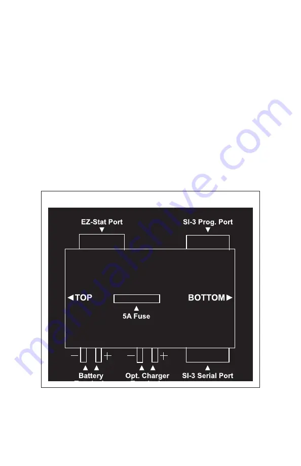
Fig . 3 .4 details the three interface communication ports which
transfers radar data from the SI-3™ antenna assembly to the EZ Stat™
and the SI-3™ programming port .
• ON/OFF: Flip the toggle switch to power on/off .
• SI-3 Prog . Port: The female 9-pin connector is used to access the
SI-3™ programming options .
• EZ Stat Port: The male 9-pin connector is used to attach the EZ
Stat™ module used to collect traffic data .
• SI Serial Port: SI-3™ is connected to this port/connector .
• Battery/Opt . Charger Terminals: plus (+) = red, minus ( - ) = black .
Figure. 3.4
Port Locations
INTERFACE BRACKET SCHEMATIC


