background image

SVR DU

AL

™ 


U

ser
’s M
anual

5

About This Manual

This manual contains valuable information to help you set up, use 
and maintain your radar so you can optimize its life and keep it at 
peak performance . Please take a moment to read through it, and 
keep it handy for future reference . 

Note the following symbols in this manual:

  Indicates a warning message about safety 

precautions .  Please read it carefully . 

  Indicates a helpful tip or precaution to note .

1.  Safety Information

All service needs should be referred back to the manufacturer .

WARNINGS 

•  Do not over voltage the radar - it can damage the unit! 
•  The SVR Dual™ is designed to operate off of standard 

+12 VDC (+9 VDC to +24 VDC) from the serial cable . 

WARNINGS

•  Opening the SVR Dual™ automatically voids any 

warranty still in effect .  There are no user serviceable 
parts inside .

•  Do not expose the SVR Dual™ to excessive moisture . 

Never submerge the device .  The unit is only water 
resistant providing the power/data cable is plugged in .

•  Do not drop the SVR Dual™ on hard surfaces since 

damage could occur . Units damaged by dropping or 
abuse are not covered for warranty repair .

    Violation of these guidelines may void the warranty .

Summary of Contents for SVR DUAL

Page 1: ...User s Manual Rev 5 2 19 SVRDUAL Surface Velocity Radar With Water Level Sensor ...

Page 2: ...ems Screen 17 4 4 1 Address 1 247 for Modbus 17 4 4 2 Software Version Unit ID 17 4 4 3 Measurement 17 4 4 4 Target Report 18 4 4 5 Target Average 19 4 4 6 Auto Manual Vertical COS Adjustment 19 4 4 7 Cosine Horizontal and Cosine Vertical 20 4 4 8 Hold Time 21 4 4 9 Update Rate 21 4 4 10 Sensitivity 21 4 4 11 Water Distance Sensor Duty Cycle 21 4 4 12 RS485 or 4 20 mA Loop 22 4 4 13 Baud Rate 22 4...

Page 3: ...tors Wind Rain Snow 38 6 Care Cleaning and Storage 38 7 Specifications 39 7 1 Antenna Parameters 39 7 2 Environment 39 7 3 Speed Range Parameters 39 7 4 Power Consumption 39 7 5 Water Distance Sensor Parameters 40 8 Legal Requirements 41 8 1 Documents 41 8 2 FCC Statement 42 8 3 Conditions 42 8 4 Installer Note 42 8 5 End User Note 42 9 Frequently Asked Questions FAQ 42 10 Warranty 43 11 Service R...

Page 4: ...many leading features such as cosine error correction for the vertical and horizontal angle positions of the transmitter to the target The SVR Dual also contains a configurable horizontal cosine adjustment that may be used when the angle of the SVR Dual is not parallel to the flow of the target If you are as pleased with its performance as we think you will be ask your Decatur sales representative...

Page 5: ...needs should be referred back to the manufacturer WARNINGS Do not over voltage the radar it can damage the unit The SVR Dual is designed to operate off of standard 12 VDC 9 VDC to 24 VDC from the serial cable WARNINGS Opening the SVR Dual automatically voids any warranty still in effect There are no user serviceable parts inside Do not expose the SVR Dual to excessive moisture Never submerge the d...

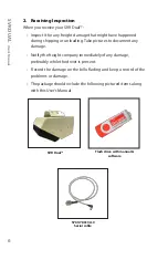
Page 6: ... Take pictures to document any damage Notify the freight company immediately of any damage preferably while the driver is present Record the damage on the bill of lading and keep a record of the problems or damage The package should include the following pictured items along with this User s Manual SVR Dual Flash drive with manual software S769 78613A 0 Serial cable ...

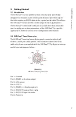
Page 7: ...r to configure certain parameters of the SVR Dual for specific applications Refer to Section 4 for configuration information 3 2 SVR Dual Panel Connector The SVR Dual housing has an 8 pin panel connector which will receive a variety of cable options The standard cable is the serial cable which comes supplied with the SVR Dual The 8 pin connector and it s pin out appears below Figure 3 2 SVR Dual H...

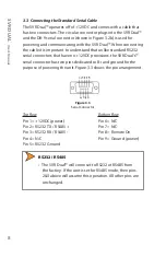
Page 8: ...ard RS232 serial connectors that have no 12VDC provisions the SVR Dual s serial connector has two pins dedicated to B and ground for the purpose of powering the unit Figure 3 3 shows the pin arrangement Figure 3 3 Serial Connector Top Row Bottom Row Pin 1 12VDC power Pin 6 N C Pin 2 RS232 TX RS485 Pin 7 N C Pin 3 RS232 RX RS485 Pin 8 Remote On Pin 4 N C Pin 9 Ground power Pin 5 RS232 Ground RS232 ...

Page 9: ...nting bracket can be attached to the top or the rear of the unit The bracket of the unit is then attached to a pipe using high strength 1 2 inch wide stainless steel adjustable hoops 3 5 Mounting Examples The following examples show standard mounting and positioning of the SVR Dual It is important to make sure that the unit is parallel with the surface of the water If need a level can be placed on...

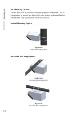
Page 10: ...he SVR Dual It is important to remember that which ever option is chosen that the SVR Dual be kept parallel with the water surface Vertical Mounting Option Figure 3 6a Vertical Mounting Option Horizontal Mounting Options Figure 3 6b Horizontal Mounting Option Figure 3 6c Horizontal Mounting Option ...

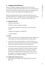
Page 11: ...RS232 adapter Configuration Program from flash drive 12V power supply 4 2 Setup 1 Connect the SVR Dual to the programming cable using the end of the cable that has the red and black wire coming out of it 2 Connect the red wire to the positive 12 VDC of the power supply and connect the black wire to the negative ground side of the power supply Do not turn the power supply on 3 Connect the other end...

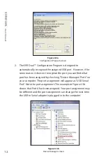
Page 12: ...the port you can find what port has been assigned by checking Device Manager Ports on your computer The port assignment will appear as USB Serial Port Note the port assignment The example in Figure 4 3b shows that Port 4 has been assigned Your port assignment may be different and the port assignment can change the next time the USB to Serial adapter is plugged in to the computer Figure 4 3b Device...

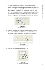
Page 13: ... the USB to Serial adapter use the port shown in Device Manager Ports Once the correct port is known the Device Manager Computer Management screens can be closed Figure 4 3c Comm port selection 4 Once the COM port has been selected left click on the Open Port button A COM port OPEN message will be displayed indicating that the COM port is now active See Figure 4 3d Figure 4 3d Press the Open Port ...

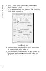
Page 14: ...ng up the SVR Dual Configuration Items dialog box Figure 4 3f Figure 4 3f Configuration Items screen 8 Select new options for programming as desired An explanation of the settings is described in Section 4 4 9 Once new options have been selected press the OK button The Configure program will upload the new settings and the SVR Dual will start ...

Page 15: ...t that the SVR Dual is to use For the SVR application only fps or m s is recommended Miles per hour Select mph Kilometers per hour Select km h Meters per second Select m s Feet per second Select fps You can set MAX and MIN speeds by changing the settings in the MAX Speed and MIN Speed window as shown in Figure 4 4 3a Figure 4 4 3a MAX and MIN setting window If your SVR is running software version ...

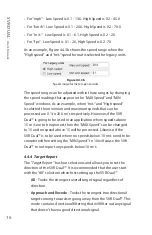
Page 16: ...wever if the SVR Dual is going to be used in an application where speeds above 15 m s are to be ignored then the MAX Speed can be changed to 15 and no speed above 15 will be processed Likewise if the SVR Dual is to be used where no speeds below 10 m s need to be considered then setting the MIN Speed to 10 will cause the SVR Dual to not report any speeds below 10 m s 4 4 4 Target Report The Target ...

Page 17: ...rectional filtering that will filter out any signal that does not have a good directional signal Figure 4 4 4 Target Report 4 4 5 Target Average On versions 3 6 and higher the ability to set the average target time has been added The target average can be set for either Instantaneous or up to 1 200 seconds Figure 4 4 5 Target Report 4 4 6 Auto Man Vertical COS Adjustment On the SVR Dual the Vertic...

Page 18: ...e flow of the river If the SVR Dual is installed so that it is aimed downstream then the cosine angle error is calculated as the difference between the vertical angle of the mounted SVR Dual and the cosine angle of the river flow Subtract the angle of the river flow from the angle of the SVR As an example if the SVR Dual s mounted vertical angle is 30 degrees and the river flow is 10 degrees then ...

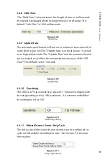
Page 19: ...s 8 seconds The Update Rate and the amount of serial port activity do not affect the measurement accuracy of the SVR Dual The default rate is 1 Second Figure 4 4 9 Update Rate 4 4 10 Sensitivity The SVR Dual has a sensitivity range of 1 100 and is shipped with the range setting at the 100 maximum It is recommended that the setting be left at 100 Figure 4 4 10 Sensitivity Setting 4 4 11 Water Dista...

Page 20: ...Baud Rate The Baud Rate can be 1200 2400 4800 9600 19200 38400 57600 or 115200 bits per second The SVR Dual always uses 8 bits no parity and one stop bit for its serial port configuration The default baud rate is 9600 Figure 4 4 13 Baud Rate 4 4 14 Serial Protocol Currently there are seven protocols available along with three options as shown in Figure 4 4 12 Figure 4 4 14 Serial Protocols options...

Page 21: ...ata 165 decimal 2 SNSN is the serial number MSB and LSB most significant byte and least significant byte of the unit 3 SS SSS is hex equivalent of speed in hex 4 CS is hex checksum of the data of A5SNSNSS SSS Example For a radar with serial number 01 Speed 05 128 m s the radar will send as HEX A5 30 31 30 35 2E 31 32 38 8F This is a polled command so you must send ASCII P01 04 CR or in hex 50 30 3...

Page 22: ...he third option is Debug and is designed for engineering use and prints out a list of variables Note User must send the exact serial number that matches what is currently programmed into the radar unit for it to transmit data otherwise the request will be ignored User has the ability to program the serial number as needed In this case the serial number becomes the MODBUS address of the radar Once ...

Page 23: ... Configuration Program screen 2 The SVR Dual Configuration Program is designed automatically recognize the USB port However if it does not you can select the port yourself For instructions on determining the correct port assignment refer to Section 4 3 point 2 Figure 4 5b Communications Port Selection 3 Once the correct port has been selected Press OPEN PORT Figure 4 5c Press the Open Port button ...

Page 24: ...down menu Figure 4 5e Press the Select Unit button 6 The SVR Dual Configure Items screen will appear Select new options as desired Refer to Section 4 3 point 6 for additional information on configuring items Once changes have been made or if no changes are needed press the OK button Figure 4 5f Configuration Items screen ...

Page 25: ...button if you want the SVR Dual to accept the changes that have been made to the Configuration Items screen and to program the SVR Dual with new firmware Figure 4 5h Program and Configure button 11 Within 3 seconds of pressing the CONFIGURE button apply power to the SVR Dual unit 12 The Configure program will update the SVR Dual with new firmware and any configuration changes made and start 4 6 Co...

Page 26: ...wed by a CR must be sent to the unit otherwise new settings will get lost on power down In the Commands list that follows the letter X will used to represent the number value that the radar responds back with due to the wide range of number possibilities 4 7 1 Commands Get Unit ID Send ASCII i CR Radar responds back with ASCII unit ID 0 255 CR LF Get Serial Number Send ASCII s CR Radar responds ba...

Page 27: ...directional X 2 Towards X 3 Away Radar responds back with ASCII OK TX CR LF Set Horizontal Cosine Angle Send ASCII H XX CR Where XX angle degrees in ASCII format Radar responds back with ASCII OK HX CR LF Set Vertical Cosine Angle Send ASCII V XX CR Where XX angle degrees in ASCII format Radar responds back with ASCII OK VX CR LF Set Hold Time Send ASCII h XXXX CR Where XXXX milliseconds in ASCII ...

Page 28: ...nsitivity to a value of 7 you must enter 07 or the value will be seen as 70 Set Speed Alarm Send ASCII A XXX CR Where XXX speed alarm in ASCII format Radar responds back with ASCII OK A CR LF Set Protocol Send ASCII P XX CR Where XX serial port protocol 00 to 99 XX 00 none XX 01 standard output for that model XX 02 FFT output XX 03 debug Radar responds back with ASCII OK PX CR LF Set Baud Rate Sen...

Page 29: ...instantaneous speed 001 100 secs of averaging NOTE Radar measurement time is 0 0625 secs 16 times per second Radar responds back with ASCII OK aX CR LF Poll Speed Only available if Radar is configured for polled mode Send ASCII P CR or CR Radar responds with speed update Reset to Factory Defaults Send ASCII X CR or ASCII x CR Radar will reset all configure items back to factory defaults and save t...

Page 30: ...nds back with current max velocity setting Minimum Velocity Setting Send ASCII cm CR Radar responds back with current minimum velocity setting Target Report Settings Send ASCII cT CR Radar responds back with the current target report setting Horizontal Angle Setting Send ASCII cH CR Radar responds back with the current horizontal angle setting Vertical Angle Setting Send ASCII cV CR Radar responds...

Page 31: ...ere the SVR is to be set up and what to do when these factors occur can greatly increase the radar s performance 5 1 How Radar Works Determining a velocity begins with the radar transmitting and directing a beam of microwave energy radio waves at an approaching or receding target When energy from this beam strikes the target a small amount of energy from this beam is reflected back to the antenna ...

Page 32: ... the most accurate information on flow rate selecting the correct location to position the SVR is important For best results the SVR should be positioned where the water flow is constant and free from disruptions Obstacles in the flow that create eddies or swirls such as areas that have large rocks or man made objects that disrupt the smooth flow should be avoided Also to be avoided are areas wher...

Page 33: ...d when setting up the SVR 5 3 Interference Sources and Remedies When properly installed and operated Doppler radar technology is extremely accurate and reliable However variations in the environment can cause situations and circumstances which can cause spurious erratic and unusually low or high velocities to ...

Page 34: ...ctual water surface velocity This condition exists whenever the target s path the water flow direction is not parallel with the radar s antenna As the horizontal yaw angle between the antenna and the target s directions of travel increases the displayed velocity decreases Ideally an angle of zero 0 is best Figure 9 2 1 An angular error occurs when the target s path is not parallel to the SI 3L s a...

Page 35: ...ce velocity speed sporadically blinks and reappears at semi random intervals This type of interference occurs when the radar loses track of a target because the target is reflecting two or more signals interfering with each other The SVR Dual is immune from multi path cancellation 5 3 5 Radio Frequency Interference RFI The system can inadvertently process radio energy as Doppler speeds including t...

Page 36: ...get can be detected however these factors will not affect accuracy 6 Care Cleaning and Storage Avoid spilling food beverages and other liquids and substances on the radar device When you are not using or transporting the device store it in its original packaging To clean the radar device use a soft clean cloth which is free of cleaning solutions ...

Page 37: ...idity 100 relative humidity Unit is weather proof not water proof 7 3 Speed Range Parameters Speed Display Ranges Minimum Maximum mph option high speed 0 2 45 mph option low speed 0 1 13 6 km h option high speed 0 2 70 km h option low speed 0 1 20 fps option low speed 0 1 20 fps option high speed 0 2 65 m s low speed 0 1 6 1 m s high speed 0 2 20 7 4 Power Consumption Parameters Power consumption ...

Page 38: ...change without notice Transmitter frequency 61 GHZ Power Transmit 10 dBm Detection Distance 0 05 to 35 meters Accuracy 2mm Beam Width horizontal vertical 8 Side Lobe Suppression horizontal vertical 15dB Continuous operation or duty cycle 10 to 100 over 1 minute is set via configuration program ...

Page 39: ...SVR DUAL User s Manual 39 8 Legal Requirements 8 1 Documents ...

Page 40: ...ply with the FCC and IC RF exposure requirements 8 5 End User Note Maintain a 20 cm separation between this device s antenna and all persons during operation in order to comply with the FCC and IC RF exposure requirements 9 Frequently Asked Questions FAQ Q My SVR Dual has poor range How can I remedy this A Make sure radar is on maximum sensitivity and make certain that the radar is oriented correc...

Page 41: ...ent found to be defective without cost to the owner providing you return the part to a Decatur authorized warranty service center The full warranty on parts and workmanship does not include normal wear and tear crushing dropping fire impact immersion misuse vandalism or damage from attempted repair or modifications by unauthorized service agents or improper voltage For repairs simply return the SV...

Page 42: ...age shipped express or next day air there will be an additional charge If you are referred to a Service Provider and your product is under warranty then once your product has been received the Service Provider will investigate the problem Once they have diagnosed the problem they will repair the product and return it to you If you are referred to a Service Provider and your unit is not under warra...

Page 43: ... to that particular sensor and only that sensor is allowed to respond An additional benefit of RS485 is noise immunity of the bus due to the differential signaling RS485 is defined as having a half duplex bus which allows just two wires to handle all communications to and from the sensors RS422 is similar to RS485 except uses 4 wires to form a full duplex path on the bus using two wires for transm...

Page 44: ... S769 78613U 0 Red Power in White Ground Brown RS485 or Analog output Blue RS232 RX input to radar Pink RS232 TX output from radar Green LVL sensor Yellow SDI 12 Grey RS485 or Analog output 14 2 S769 78614 0 Cable has the same pin out as the S769 78613A 0 Refer to section 3 3 In addition it has a black wire that connects to the negative and red wire that connects to the positive of a 12 VDC supply...

Page 45: ...www DecaturElectronics com 800 428 4315 ...

Reviews: