Operations Manual USB Photo Relay Card
DECISION Computer International
- 9 -
9
2.5 Connector Assignments
1.
TB1 Relay Output and Power Signal Assignments
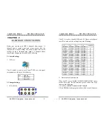
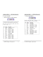
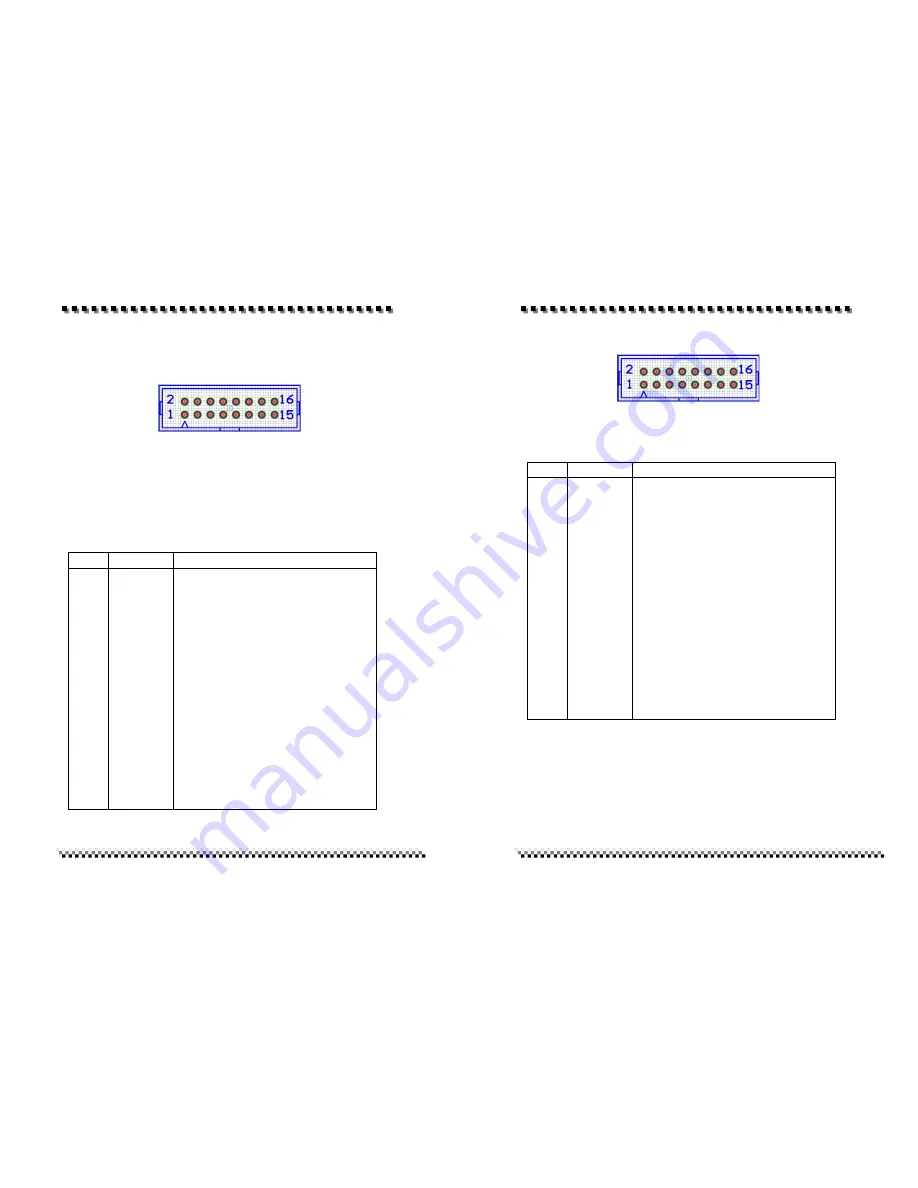
The relay output signals and external power signal are assigned
in TB1 connector, its pin assignments are show in the below.
Where (NO-00, COM-00, NC-00) is OUT00, (NO-01, COM-
01, NC-01) is OUT01, … etc.
Pin
Signal
Description
1
2
3
4
5
6
7
8
9
10
11
12
13
14
15
16
EXT+5V
SGND
NO-0
COM-0
NC-0
NO-1
COM-1
NC-1
+5V
SGND
NO-2
COM-2
NC-2
NO-3
COM-3
NC-3
Ex5V 1A Power
Signal Ground
Relay Ch. 0 - Output
Relay Ch. 0 - Output
Relay Ch. 0 - Output
Relay Ch. 1 - Output
Relay Ch. 1 - Output
Relay Ch. 1 - Output
+5V POWER
Signal Ground
Relay Ch. 2 - Output
Relay Ch. 2 -Output
Relay Ch. 2 - Output
Relay Ch. 3 - Output
Relay Ch. 3 - Output
Relay Ch. 3 - Output
Operations Manual USB Photo Relay Card
DECISION Computer International
10
2.
TB2 Input Signal Assignments
The photo isolator input signal is assigned in the TB2
connector, its pin assignments are show in the below.
Pin
Signal
Description
1
2
3
4
5
6
7
8
9
10
11
12
13
14
15
16
SGND
+5V
IN-3+
IN-3-
IN-2+
IN-2-
SGND
+5V
SGND
+5V
IN-1+
IN-1-
IN-0+
IN-0-
SGND
+5V
Signal Ground
+5V POWER
Opto-isolator Ch. 3 + Input
Opto-isolator Ch. 3 - Input
Opto-isolator Ch. 2 + Input
Opto-isolator Ch. 2 - Input
Signal Ground
+5V POWER Signal
Ground
+5V POWER
Opto-isolator Ch. 1 + Input
Opto-isolator Ch. 1 - Input
Opto-isolator Ch. 0 + Input
Opto-isolator Ch. 0 - Input
Signal Ground
+5V POWER

