®
88
STEP 1: Check that the dimensions of the cut-out are as shown on the technical drawing provided with
the fireplace. All corners of the cut-out must be in a 90° angle and all surfaces in level. Make sure that
there is an earthed power socket inside the wall cut at the bottom to the left – ideally placed below the
level of the tank (lower than 203mm). Check furthermore, that the cut-out has been prepared in line with
the desired way of installation (i.e. either with the base plate resting on the surrounding surface, with the
edges of the cut-out prepared with a router or using the mounting brackets included).
STEP 2: Lift the Decoflame Denver e-Ribbon Fire carefully out of its packaging holding it at the straps. Do
not lift it by inserting your hands into the openings of the lids left and right. Place the Denver e-Ribbon
Fire™ carefully on a level surface. Do not tilt it. Move the Denver e-Ribbon Fire™ closer to the cut-out
and insert the plug into the socket. If necessary, switch on the socket. Still holding the fire at the straps,
carefully lift it into the cut-out.
STEP 3: If the fireplace is positioned as desired, open the lid to the left, flip it over and switch the elec-
tronics on using the ON/OFF button. The straps can now be removed. Should the display not be lit, lift
out the fireplace using the straps in order to check the power socket and cable.
STEP 4: If the Denver e-Ribbon Fire has been delivered with glass screen(s) with glued-on glass hold-
ers, please carefully fit the glass screen(s) by inserting the glass holders into the holes in the base plate.
Please avoid scratching the base plate.
STEP 5: Turn on the display. Fill in the right amount of bioethanol by verifying the level on the display.
Start the fireplace by pressing the ON icon on the display.
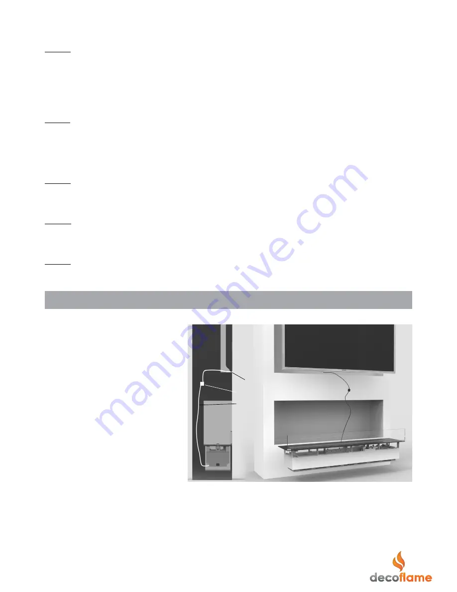
4.5. INSTALLATION OF THE TV TEMPERATURE SENSOR
®
1. Drill a Ø6mm hole in the wall behind
the TV approx. 50mm up from the bottom
of the TV.
2. Remove the TV temperature sensor from
its plastic bag.
3. Insert the sensor (1) tip from behind of
the cut-out wall. Approx. 10mm of the tip
should stick out of the wall. Alternatively,
pull it out completely and fix it to the low-
est point of the TV at its back (e.g. using
tape).
4. Seal the space (if there is any) in a whole
around the TV temp. sensor in order to avoid
the sensor falling back inside the wall.
5. Connect the end of the cable of the TV
Temperature sensor to the white connec-
tor box (2) at the end of the cable (3) ex-
iting at the back of the base plate (locat-
ed around the center). The blue wire can
be connected to any of the wires (either
white or red).
6. Plug the power cable of the fireplace (exiting to the left of the base
plate) into the socket (switch socket on if required).
7. Lift the base plate towards the cut-out and make sure the cables is
not trapped or bended.
8. Release the base plate carefully into its position inside the cut-out,
taking care not to scratch the paint.
TV temp. sensor (1)
Connector box (2)
Cable (3)
Cut-out
Cut-out
Figure 1.6


