


42
4
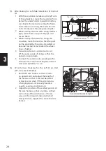
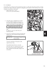
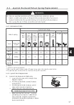
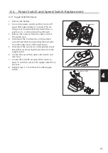
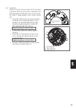
4.3.2. Switch Extension Harness Installation
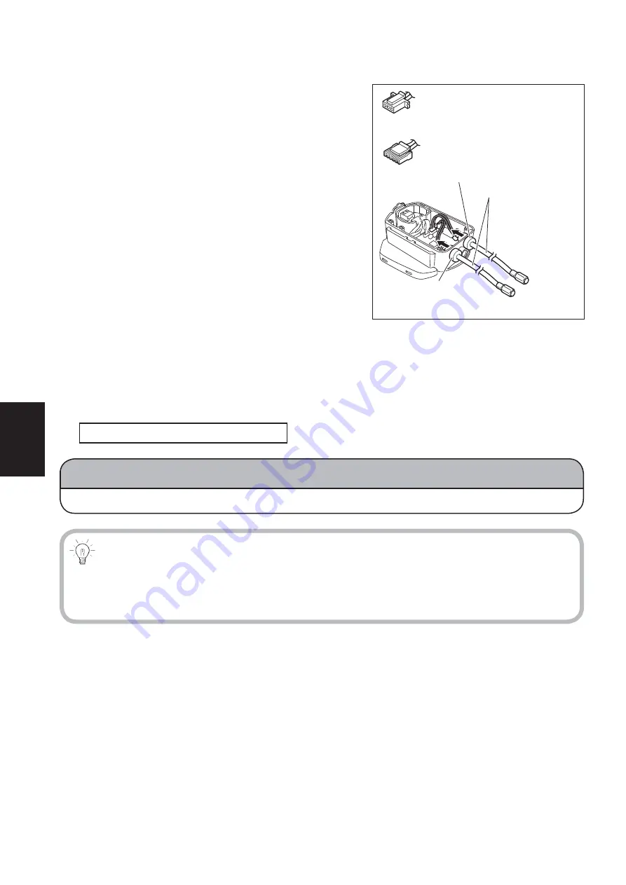
1 Insert the switch extension harnesses into the
switch case from outside the case. Fit the grom-
mets securely into the case.
3-pin connector for the power side
5-pin connector for the speed side
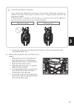
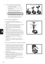
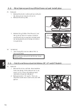
2 Connect the 2 connectors on the switch exten-
sion harnesses to the printed circuit board.
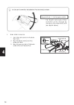
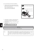
3 Connect the 3 connectors on the under cover of
the switch case.
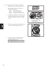
4 Tighten the 6 screws on the under cover of the
switch case.
Tightening torque: 1.1 to 1.4 Nm
3-pin connector for the power side
5-pin connector for the speed side
Grommet
Grommet
Switch extension harness
Speed side
Power side
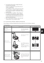
NOTICE
Note that the switch extension harnesses are not waterproof.
•
When changing the speed switch to the switch ex tension harness, be sure to
use JW Smart Tune and change the setting for the speed switch type to “Push-
type switch”. For instructions, refer to the JW Smart Tune Operation Manual.
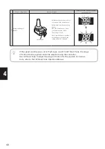
•
Use an alternate switch for the power side and a momentary switch for the speed
side.


