


43
4
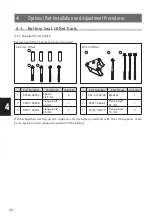
4.4. Hand Rim Replacement (20", 22", and 24" Models)
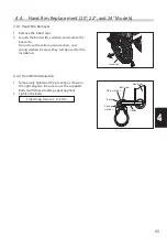
4.4.1. Hand Rim Removal
4.4.2. Hand Rim Installation
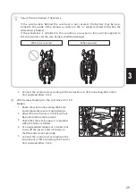
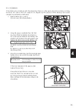
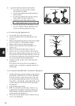
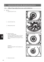
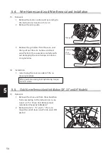
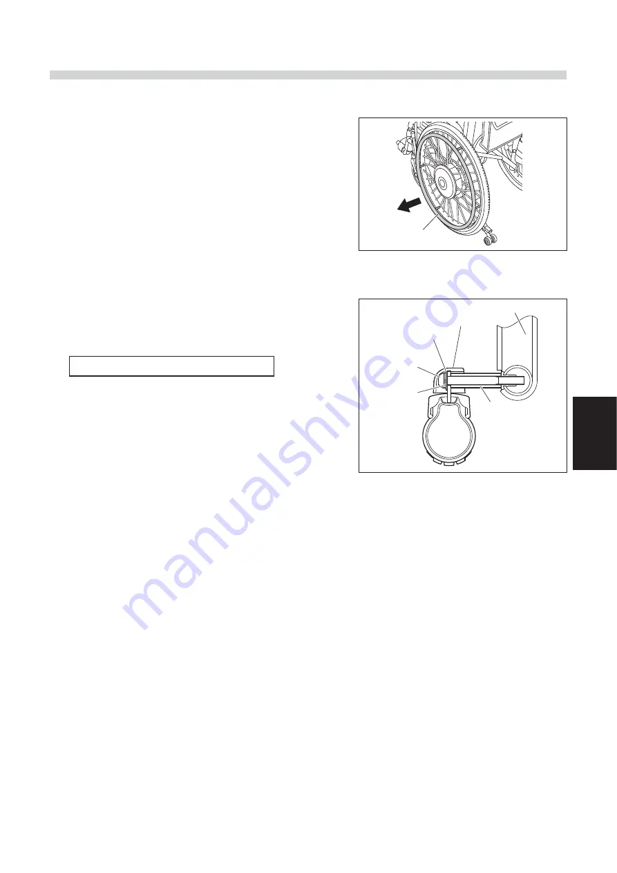
1 Remove the 6 bolt caps.
2 Loosen the bolts with a wrench and remove the
hand rim.
Do not lose the collars, plain washers, and
spring washers because they will be used for the
installation.
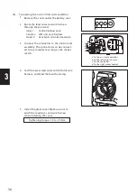
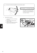
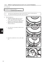
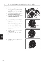
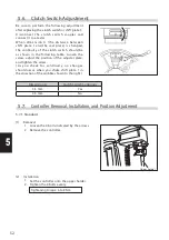
1 Temporarily tighten at the 6 locations shown in
the right diagram. Be sure to use the supplied
bolts (with thread-locking agent applied).
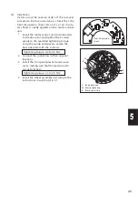
2 Tighten the bolts.
Tightening torque: 4 to 5 Nm
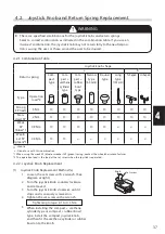
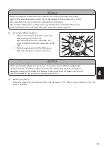
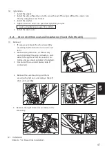
Hand rim
Hand rim
Bolt cap
Plain washer
Bolt
Collar
Spring
washer


