48
5
5.3. Motor Control Unit (Printed Circuit Board) Removal and Installation
(1) Removal
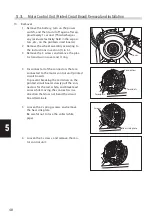
1 Remove the battery, turn on the power
switch, and then turn it off again after ap-
proximately 1 second. (This discharges
any residual electricity held in the capaci-
tors, etc., on the printed circuit board.)
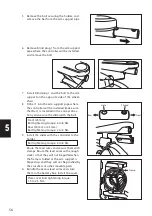
2 Remove the wheel assembly according to
the instructions in section (1) in 5.1.
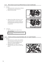
3 Remove the 3 screws and remove the plas-
tic transmission cover and O ring.
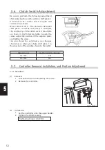
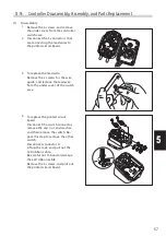
4 Disconnect all of the connectors that are
connected to the motor control unit (printed
circuit board).
To prevent breaking the terminals on the
printed circuit board, slowly pull the con-
nectors for the red, white, and black lead
wires while moving the connectors in a
direction that does not bend the circuit
board terminals.
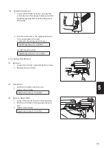
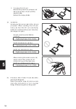
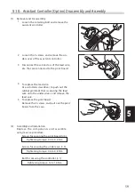
5 Loosen the 2 spring screws, and remove
the heat sink plate.
Be careful not to lose the collar (white
pipe).
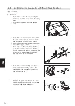
6 Loosen the 3 screws, and remove the mo-
tor control unit.
Cover
Terminals
Connectors
Terminals
Screws
Heat sink plate

