


50
5
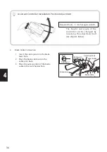
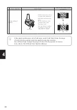
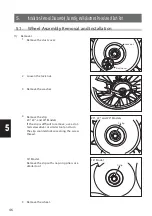
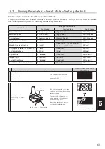
5.4. Wire Harness and Lead Wire Removal and Installation
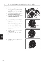
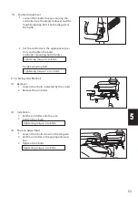
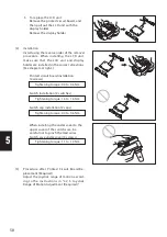
(1) Removal
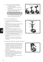
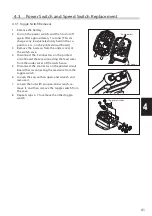
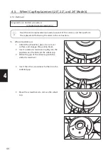
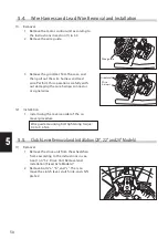
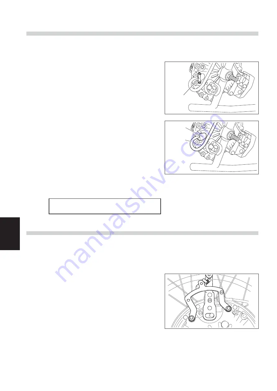
5.5. Clutch Lever Removal and Installation (20", 22" and 24" Models)
1 Remove the motor control unit according to
the instructions in section (1) in 5.3.
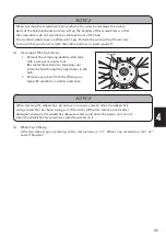
2 Remove the wire guide.
3 Remove the grommet from the case, and
then pull out the wire harness and lead
wire. Perform this operation carefully with-
out damaging the wire harness connector
or signal wires.
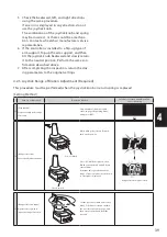
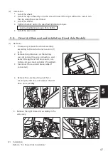
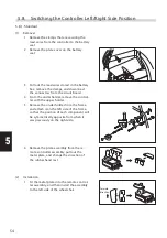
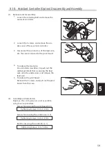
1 Remove the drive unit from the wheelchair
frame according to the instructions in sec-
tion (1) in “5.2. Drive Unit Removal and
Installation (Fixed Axle Models)”.
2 Remove bolts “a”, “b”, and “c”. Then, re-
move the clutch lever, clutch link, and shift
plate 2.
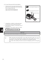
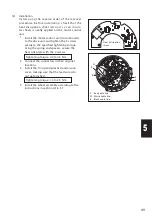
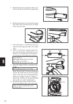
1 Install using the reverse order of the re-
moval procedure.
Wire guide mounting bolt tightening torque:
0.4 to 0.6 Nm
(2) Installation
(1) Removal
a
b
c
Wire guide
Grommet
Wire
harness


