58
5
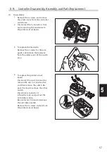
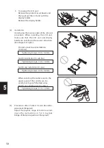
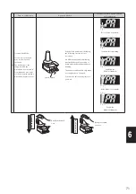
5 To replace the LCD unit:
Remove the printed circuit board, and
then pull out the LCD unit with the
display holder.
Remove the display holder.
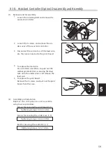
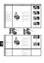
Printed circuit board installation
(4 screws)
Tightening torque: 0.4 to 0.6 Nm
Switch installation (2 switches)
Tightening torque: 1.4 to 1.6 Nm
Switch cap installation (2 caps)
Tightening torque: 0.4 to 0.6 Nm
When installing the under cover to the
upper cover of the switch case, be
careful not to pinch the lead wires.
Switch case under cover (6 screws)
Tightening torque: 1.1 to 1.4 Nm
(2) Installation
Install using the reverse order of the removal
procedure. When installing the LCD unit,
make sure that the LCD unit and display
holder are installed in the correct directions.
(See diagram at right.)
(3)
Procedure af ter Printed Circuit Board Re -
placement (Required)
Adjust the joystick range of motion accord-
ing to the instruc tions in “4. 2. 5. Joystick
Range of Motion Adjustment (Required)”.

