background image

1

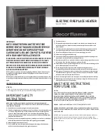
ElEctric FirEplacE HEatEr

Model: M405-48FBK 

iMpOrtaNt:

NOtE: DO NOt rEtUrN UNit tO tHE StOrE 

BEFOrE cONtactiNG OUr cUStOMEr SErVicE 

DEpartMENt. DO NOt DiSpOSE OF yOUr 

cartONS UNtil yOU arE cOMplEtEly SatiSFiED 

witH yOUr NEw FirEplacE HEatEr.

plEaSE NOtE: wHEN yOU OpEN tHE cartON carEFUlly cHEck 

tHE UNit aND MakE SUrE tHErE iS NO DaMaGE. iF yOU HaVE 

aNy prOBlEMS witH aSSEMBliNG tHE UNit, witH HOw tHE 

VariOUS FUNctiONS wOrk Or witH DaMaGE Or MiSSiNG partS, 

plEaSE GO tO OUr wEBSitE www.qUalitycraFt.cOM aND 

click ON cUStOMEr SUppOrt. 

NOtE: light bulbs may become loose during shipping. if the flame effect is dim or does not 

work, please check that light bulb or bulbs are finger tight in socket. See instructions for 

replacing bulb or bulbs.
NOtE: the electric fireplace heater may emit a slight harmless odor when first turned on. this 

is caused by activating the internal heater components for the first time and should not occur 

again.

INSTRUCTION MANUAL

attENtiON: 

1.  Find a location for the fireplace heater that is protected from direct sunlight.
2. Do not plug the unit into the power outlet before reading all instructions.

IMPORTANT SAFETY 

INSTRUCTIONS

wHEN USiNG ElEctrical appliaNcES, BaSic prEcaUtiONS SHOUlD alwayS BE 

FOllOwED tO rEDUcE tHE riSk OF FirE, ElEctric SHOck, aND iNJUry tO pErSONS, 

iNclUDiNG tHE FOllOwiNG:
1)   read all instructions before using this electric fireplace heater.
2)   this electric fireplace heater is hot when in use. to avoid burns, do not let bare skin touch 

hot surfaces. the grill directly in front of the heater outlet becomes hot during heater 
operation. keep combustible materials, such as furniture, pillows, bedding, papers, 
clothes, and curtains at least 3 ft (0.9 m) away from the front of the unit and keep them 
away from the sides and rear. 

3)   Extreme caution is necessary when any heater is used by or near children or individuals 

with disabilities and whenever the fireplace is left operating and unattended. 

4)   always unplug fireplace when not in use.
 5)   Do not operate any electric fireplace with a damaged cord or plug or after the heater 

malfunctions, has been dropped or damaged in any manner. 

6)   Do not use outdoors. 
7)   this electric fireplace heater is not intended for use in bathrooms, laundry areas and 

similar indoor locations. Never locate heater where it may fall into a bathtub or other 
water container. 

8)   Do not run cord under carpeting. Do not cover cord with throw rugs, runners, or similar 

coverings. arrange cord away from traffic area and where it will not be tripped over. 

9)   to disconnect fireplace, turn controls to off, then remove plug from outlet. 
10)  connect to properly grounded outlets only.
11)   Do not insert or allow foreign objects to enter any ventilation or exhaust opening as this 

may cause an electric shock or fire, or damage the heater. 

12)  to prevent a possible fire, do not block air intakes or exhaust in any manner. Do not use on 

soft surfaces, like a bed, where openings may become blocked. 

13)  a heater has hot and arcing or sparking parts inside. Do not use it in areas where gasoline, 

paint, or flammable liquids are used or stored. 

14)  Use this fireplace heater only as described in this manual. any other use not 

recommended by the manufacturer may cause fire, electric shock, or injury to persons. 

15)  avoid the use of an extension cord because the extension cord may overheat and cause 

a risk of fire. However, if you have to use an extension cord, the cord shall be No.14 awG 
minimum size and rated not less than 1875 watts.

16)  caution: Do not plug this product into a receptacle controlled by a wall switch or dimmer.
17)  when storing or transporting the unit and cord, keep in a dry place, free from excessive 

vibration and store so as to avoid damage.

SAVE THESE INSTRUCTIONS  

FOR FUTURE USE.

caUtiON:
iF yOU USE tHiS HEatEr iN cONJUNctiON witH a tHErMal cONtrOl, a prOGraM 

cONtrOllEr, a tiMEr Or aNy OtHEr DEVicE tHat SwitcHES tHE HEatEr ON 

aUtOMatically, rEMEMBEr tO OBSErVE all SaFEty warNiNGS at all tiMES. tHE 

FirEplacE HEatEr HaS SaFEty OVErHEat prOtEctiON. iF tHE OVErHEat prOtEctiON 

tripS, SwitcH OFF all SwitcH BUttONS aND wait apprOxiMatEly 5 - 10 MiNUtES. it 

SHOUlD rESEt aUtOMatically ONcE tHE UNit cOOlS DOwN.

warNiNG - DO NOt lOaD MOrE tHaN 22.7 kG (50 lBS) ON tHE tOp SHElF.

warNiNG: prOcEDUrES aND tEcHNiqUES iF NOt carEFUlly FOllOwED will rESUlt iN 

DaMaGE tO tHE EqUipMENt aND will ExpOSE tHE USEr tO tHE riSk OF SEriOUS iNJUry, 

illNESS Or DEatH. 

A 15 AMP circuit is required to operate this heater. If the breaker trips when the heater 
is used, then you may need to move the heater to another location or unplug other 
appliances that are on the same circuit. If you require an extension cord use one that is 
rated at 1875 watts. 

Summary of Contents for M405-48FBK

Page 1: ...ions Neverlocateheaterwhereitmayfallintoabathtuborother watercontainer 8 Donotruncordundercarpeting Donotcovercordwiththrowrugs runners orsimilar coverings Arrangecordawayfromtrafficareaandwhereitwillnotbetrippedover 9 Todisconnectfireplace turncontrolstooff thenremoveplugfromoutlet 10 Connecttoproperlygroundedoutletsonly 11 Donotinsertorallowforeignobjectstoenteranyventilationorexhaustopeningasth...

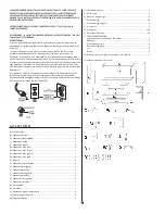
Page 2: ...or 1 N Right door 1 O Shelf supporting pins 8 Pa Door handle screws 2 Pb Door handles 2 Q Door hinges 4 R Wire passage 1 S L mounting brackets 2 T Mounting screws 16 U Long mounting screws 3 V Short screws 5 W Long screws 108 X Plastic connectors 36 Y SELF REPAIR SET Touch up repair paint bottle 1 L shape brackets 2 Screws for L shape brackets 8 Plastic connector 1 Screws 3 Nuts 3 Z1 Foam tape for...

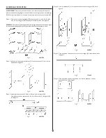
Page 3: ...tep 4 Attach panel G H I and J to panel D with 8 long screws W See Fig D Fig D BACK Step 5 Attach panel F to panel C with 3 long mounting screws U as shown in Fig E Fig E FRONT Step 6 Attach panel K in between panel G and I Attach panel L in between panel J and H See Fig F Fig F BACK Step 7 Attach panel C to panels G H I and J with 8 long screws W as shown in Fig G Fig G BACK Step 8 Attach panel B...

Page 4: ... door handles Pb to left and right door M and N with door handle screws Pa See Fig L Fig L FRONT Step 13 Attach left and right door M and N to panels G and H with 8 mounting screws T 2 screws on each door hinge as shown in Fig M Fig M FRONT Step 14 Foam tape Z1 has been provided to protect your fireplace mantel Remove the backing paper from the foam tape Step 15 Attached the foam tape to the left ...

Page 5: ... switch while the 0 I switch is in the ON position for low heat The indicator light will turn on 1500W For high heat press this switch while the 0 I switch and the 750W switch are in the ON position for high heat The indicator light will turn on To adjust the temperature to your individual requirements turn the temperature control dial to the right clockwise to increase the desired temperature and...

Page 6: ... if necessary REPAIRS If any problems are found with the original parts during mantel assembly such as the panels cannot be installed with the plastic connector Try to solve by one of the following methods Tools required electric drill drill bits 10 mm 3 4 in or 2 mm 1 16 in pencil hammer Phillips screwdriver safety goggles and gloves if necessary WARNING Wear goggles before you start drilling Opt...

Page 7: ...ouldfailtooperatecorrectlywithinoneyearfromthedateof purchase pleasegotoourwebsitewww qualitycraft comandclickoncustomersupport Wewill atourdiscretion eitherrepairorreplacetheunit Itwillhavetobereturnedtous freightprepaidandwewillreturntherepairedorreplacedunittoyoufreightprepaid The company ssoleobligationistorepairorreplacetheunit Warranty Claim Procedure Ifaclaimabledefectoccurs pleasefilloutac...

Page 8: ...heoulecordond alimentationest endommagé ouaprèsl apparitiond undéfautdefonctionnement ouaprèsqu ilaitété échappéausolouendommagéd unemanièrequelconque 6 N utilisezpascetappareilàl extérieur 7 Lefoyerélectriquen estpasconçupourêtreutilisédansunesalledebain unesallede lavageouunautreemplacementintérieursemblable N installezjamaislefoyerlàoùil risqueraitdetomberdansunebaignoireouunautrecontenantd eau...

Page 9: ...terre Si une prise de courant à trois broches de mise à la terre effective est disponible n utilisez pas d adaptateur Un circuit de 15 ampères est requis pour utiliser ce foyer Si le disjoncteur déclenche lorsque vous utilisez l appareil il vous faudra peut être le déplacer ou débrancher d autres appareils partageant le même circuit Si vous devez utiliser un câble de rallonge il doit avoir une pui...

Page 10: ...plastiquejusqu àcequ ilsoitpossibled installerlespanneauxoulesvis Fig A arrière Étape 2 Installer les huit supports de tablette O sur les panneaux G H I et J comme illustré dans la figure B Fig B arrière Étape 3 Assembler les panneaux Da Db Dc et Dd avec les 4 vis longues W Fixer le panneau D aux panneaux Da Db Dc et Dd avec les 12 vis longues W Voir la figure C Fig C arrière Étape 4 Fixer les pan...

Page 11: ...u B entre les panneaux G et H Voir la figure H Fig H arrière Étape 9 Fixer le panneau A aux panneaux G et H avec quatre vis longues W comme illustré dans la figure I Fig I arrière Étape 10 Fixer le guide câble R au panneau B comme illustré dans la figure J Fig J façade Étape 11 Fixer les panneaux E au foyer comme illustré dans la figure K Fig K façade ...

Page 12: ...ré dans la figure N Le ruban mousse doit être apposé à environ 10 15 mm 0 4 0 6 po du bord avant du foyer encastrable Fig N Étape 16 S assurer que le ruban mousse recouvre complètement les deux rebords comme illustré dans la figure O Fig O arrière Étape 17 Encastrer soigneusement le foyer dans l ouverture à l arrière du manteau La partie avant doit être de niveau avec la partie avant du manteau Vo...

Page 13: ...a commande d intensité vers la droite ou vers la gauche pour obtenir l intensité de flamme souhaitée La commande d intensité ne peut être utilisée que lorsque l interrupteur de marche arrêt 0 I est réglé sur la position de marche Remarque Lorsque l interrupteur marche arrêt 0 I est réglé sur la position d arrêt toutes les autres fonctions de chauffage s arrêtent même si les interrupteurs sont régl...

Page 14: ...n plastique et maintenez le en place avec les vis comme montré à la figure D Fig D arrière Option 2 Utiliser les petites équerres et les vis 1 Placer une petite équerre sur le meuble tel qu illustré et faire une marque pour définir les orifices à percer sur le manteau tel qu illustré à la Fig E Fig E 2 Percer les orifices d un diamètre de 2 mm 1 16 po et d une profondeur de 8 mm 5 16 po sur le man...

Page 15: ...craft com en cliquant sur Soutien à la clientèle Avant d appeler pour présenter votre réclamation veuillez vous assurer d avoir en main 1 La description de le foyer électrique 2 La preuve d achat 3 Les détails concernant le défaut 4 Nom et adresse du propriétaire Les réclamations doivent être complétées par écrit et retournées dans un délai de six 6 mois de l apparition du défaut Le manque de se c...

Page 16: ...irelibre 7 Estachimeneanohasidoconcebidaparausarencuartosdebaño lavaderosyáreas interioressimilares Nuncacoloquelachimeneadondesepuedacaeralabañerauotro lugardondeseacumuleelagua 8 Nopaseelcordónpordebajodelaalfombra Nocubraelcordónconalfombraspequeñas alfombrillasdepasilloocubiertassimilares Pongaelcordónlejosdeláreadetráficoy dondenoseaposibletropezarconél 9 Paradesconectarlachimenea gireloscont...

Page 17: ...erior 1 B Panel trasero superior 1 C Panel central 1 D Panel inferior 1 Da Panel base delantero 1 Db Panel base trasero 1 Dc Panel base izquierdo 1 Dd Panel base derecho 1 E Estantes 2 F Panel delantero central 1 G Panel lateral izquierdo 1 H Panel lateral derecho 1 I Panel izquierdo interior 1 J Panel derecho interior 1 K Panel posterior izquierdo 1 L Panel posterior derecho 1 M Puerta izquierda ...

Page 18: ...tantes O a los paneles G H I y J como se muestra en la fig B Fig B TRASERO Paso 3 Sujete los paneles Da Db Dc y Dd con 4 tornillos largos W Sujete el panel D a los paneles Da Db Dc y Dd con 12 tornillos largos W Vea la fig C Fig C TRASERO Paso 4 Sujete los paneles G H I y J al panel D con 8 tornillos largos W Vea la fig D Fig D TRASERO Paso 5 Sujete el panel F al panel C con 3 tornillos de montaje...

Page 19: ...B entre los paneles G y H Vea la fig H Fig H TRASERO Paso 9 Sujete el panel A a los paneles G y H con 4 tornillos largos W como se muestra en la fig I Fig I TRASERO Paso 10 Sujete el conducto con los cables R al panel B como se muestra en la fig J Fig J delantero Paso 11 Sujete el panel E a la unidad como se muestra en la fig K Fig K delantero ...

Page 20: ...fig N La cinta de espuma tendrá una separación de 10 15 mm 0 4 0 6 pulg del borde delantero del inserto Fig N Paso 16 Procure que la cinta de espuma cubra completamente ambos rebordes laterales como se muestra en la fig O Fig O TRASERO Paso 17 Coloque cuidadosamente el inserto en la abertura de la unidad de la parte trasera de la repisa La parte delantera del inserto debe estar nivelada con la par...

Page 21: ...pagarán pero el ventilador seguirá funcionando Regule esta perilla para volver a encender el calefactor Gire el dial del atenuador hacia la derecha o la izquierda para obtener la intensidad de llama deseada El interruptor del atenuador solo se puede usar cuando el interruptor 0 I está en la posición de encendido Nota Cuando el interruptor O I está apagado todas las demás funciones del calefactor s...

Page 22: ... la fig C 4 Sujeteelconectorplásticoyasegurecontornillos comosemuestraenlafig D Fig D Opción 2 Utilice los soportes largos pegueños y los tornillos argos 1 Coloque el soporte largo pegueño en la unidad como se muestra y marque los agujeros de perforación en la repisa como se muestra en la fig E Fig E TRASERO 2 En la repisa perfore agujeros de 1 16 pulg 2 mm de diámetro y de 5 16 pulg 8 mm de profu...

Page 23: ...om y haga clic en ayuda al cliente Antes de efectuar una llamada de reclamación asegúrese de tener a mano 1 La descripción del chimenea eléctrica 2 El comprobante de venta 3 Los detalles del defecto 4 El nombre y la dirección del dueño Las reclamaciones deben completarse por escrito y enviarse en un plazo de seis 6 meses a partir de la aparición del defecto El incumplimiento de esta cláusula anula...

Reviews: