background image

1

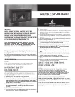
ElEctric FirEplacE HEatEr

Model: MM433L-60EBK (NDF-120B)

iMpOrtaNt:

NOtE: DO NOt rEtUrN UNit tO tHE StOrE 

BEFOrE cONtactiNG OUr cUStOMEr SErVicE 

DEpartMENt. DO NOt DiSpOSE OF yOUr 

cartONS UNtil yOU arE cOMplEtEly SatiSFiED 

witH yOUr NEw FirEplacE HEatEr.

NOtE: light bulbs may become loose during shipping. if the flame effect is dim or does 

not work, please check that light bulb or bulbs are finger tight in socket. See instructions 

for replacing bulb or bulbs.
NOtE: the electric fireplace heater may emit a slight harmless odor when first turned on.  

this is caused by activating the internal heater components for the first time and should 

not occur again.

INSTRUCTION MANUAL

attENtiON: 

1.  Find a location for the fireplace heater that is protected from direct sunlight.
2. Do not plug the unit into the power outlet before reading all instructions.

IMPORTANT SAFETY 

INSTRUCTIONS

wHEN USiNG ElEctrical appliaNcES, BaSic prEcaUtiONS SHOUlD alwayS BE 

FOllOwED tO rEDUcE tHE riSk OF FirE, ElEctric SHOck, aND pErSONal iNJUry, 

iNclUDiNG tHE FOllOwiNG:
1)   read all instructions before using this electric fireplace heater.
2)   this electric fireplace heater is hot when in use. to avoid burns, do not let bare skin 

touch hot surfaces. the grill directly in front of the heater outlet becomes hot during 
heater operation. keep combustible materials, such as furniture, pillows, bedding, 
papers, clothes, and curtains at least 3 ft (0.9 m) away from the front of the unit and 
keep them away from the sides and rear. 

3)   Extreme caution is necessary when any heater is used by or near children or 

individuals with disabilities and whenever the fireplace is left operating and 
unattended. 

4)   always unplug the fireplace when not in use.
 5)   Do not operate any electric fireplace with a damaged cord or plug or after the heater 

malfunctions, has been dropped or damaged in any manner.  

6)   Do not use outdoors. 
7)   this electric fireplace heater is not intended for use in bathrooms, laundry areas and 

similar indoor locations. Never locate the heater where it may fall into a bathtub or 
other water container. 

8)   Do not run the cord under carpeting. Do not cover the cord with throw rugs, runners, 

or similar coverings. arrange the cord away from traffic areas and where it will not be 
tripped over. 

9)   to disconnect the fireplace, turn controls to off, then remove the plug from the outlet. 
10)  connect to properly grounded outlets only.
11)  Do not insert or allow foreign objects to enter any ventilation or exhaust opening,  

as this may cause an electric shock or fire, or damage the heater. 

12)  to prevent a possible fire, do not block air intakes or exhaust in any manner. Do not 

use on soft surfaces, like a bed, where openings may become blocked. 

13)  a heater has hot and arcing or sparking parts inside. Do not use it in areas where 

gasoline, paint, or flammable liquids are used or stored. 

14)  Use this fireplace heater only as described in this manual. any other use not 

recommended by the manufacturer may cause fire, electric shock, or personal 
injury.

15)  avoid the use of an extension cord because the extension cord may overheat and 

cause a risk of fire. However, if you have to use an extension cord, the cord shall be 
No.14 awG minimum size and rated not less than 1875 watts.

16)  caution: Do not plug this product into a receptacle controlled by a wall switch or 

dimmer.

17)  when storing or transporting the unit and cord, keep in a dry place, free from 

excessive vibration and store so as to avoid damage.

SAVE THESE INSTRUCTIONS  

FOR FUTURE USE.

caUtiON:
iF yOU USE tHiS HEatEr iN cONJUNctiON witH a tHErMal cONtrOl, a prOGraM 

cONtrOllEr, a tiMEr Or aNy OtHEr DEVicE tHat SwitcHES tHE HEatEr ON 

aUtOMatically, rEMEMBEr tO OBSErVE all SaFEty warNiNGS at all tiMES. tHE 

FirEplacE HEatEr HaS SaFEty OVErHEat prOtEctiON. iF tHE OVErHEat prOtEctiON 

tripS, SwitcH OFF all SwitcH BUttONS aND wait apprOxiMatEly 5–10 MiNUtES. it 

SHOUlD rESEt aUtOMatically ONcE tHE UNit cOOlS DOwN.

warNiNG: DO NOt lOaD MOrE tHaN 22.7 kG (50 lBS) ON tHE tOp SHElF.
warNiNG: prOcEDUrES aND tEcHNiqUES iF NOt carEFUlly FOllOwED will rESUlt iN 

DaMaGE tO tHE EqUipMENt aND will ExpOSE tHE USEr tO tHE riSk OF SEriOUS iNJUry, 

illNESS Or DEatH. 

A 15 AMP circuit is required to operate this heater. If the breaker trips when the heater 
is used, then you may need to move the heater to another location or unplug other 
appliances that are on the same circuit. If you require an extension cord use one that is 
rated at 1875 watts. 

design forward living

PLEASE NOTE: WHEN YOU OPEN THE CARTON CAREFULLY CHECK THE UNIT 

AND MAKE SURE THERE IS NO DAMAGE. IF YOU HAVE ANY PROBLEMS WITH 

THE UNIT, WITH HOW THE VARIOUS FUNCTIONS WORK, DAMAGED OR MISSING 

PARTS PLEASE CALL 1-844-455-4621  IMMEDIATELY FOR SERVICE. 

Summary of Contents for MM433L-60EBK

Page 1: ...rolstooff thenremovetheplugfromtheoutlet 10 connecttoproperlygroundedoutletsonly 11 Donotinsertorallowforeignobjectstoenteranyventilationorexhaustopening asthismaycauseanelectricshockorfire ordamageth...

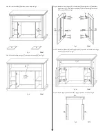
Page 2: ...panel 1 E Shelves 2 F Left side panel 1 G Right side panel 1 H Left front panel 1 I Right front panel 1 J Left inner panel 1 K Right inner panel 1 L Left back panel 1 M Right back panel 1 N Left door...

Page 3: ...connector See Fig A NOTE If the screw s do not fit during assembly loosen the 2 screws to adjust the plastic connector until the panel screws can be installed Fig A BACK Step 2 Attach 8 shelf support...

Page 4: ...er back panel B See Fig F Fig F BACK Step 7 Attach the left front panel H to the left side panel F with 3 long screws W Attach the right front panel I to the right side panel G with 3 long screws W Se...

Page 5: ...es Tc to the left door N and right door O with 8 door hinge screws Te Attach the door handles Ta to the left and right doors with 2 door screws Tb See Fig L Fig L FRONT Step 13 Attach the left door N...

Page 6: ...e front of insert should be flush with the front of the mantel See Fig R Fig R Back Step 20 Once the insert is in place attach 2 L mounting brackets Va with 2 short screws Vb onto the base panel D 1 s...

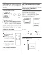
Page 7: ...l beep Press again to turn off the fireplace the fan will continue to work for 5 seconds without heat Press this button once to turn on the flame effect The unit will beep Press again to increase the...

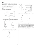
Page 8: ...with a hammer as shown in Fig C 4 Attach the plastic connector and lock in place with the screw as shown in Fig D Fig D BACK Option 2 Use the small L brackets and screws 1 Place the small L bracket on...

Page 9: ...wrong power source Light bulbs are not covered by this warranty The warranty is for homeowner use only and does notcover units used in commercial situations WARRANTY CLAIM PROCEDURE If a claimable de...

Page 10: ...de lavageouunautreemplacementint rieursemblable N installezjamaislefoyerl o il risqueraitdetomberdansunebaignoireouunautrecontenantd eau 8 N acheminezpaslecordond alimentationdel appareilsousdestapiso...

Page 11: ...illustration A ci dessous Un adaptateur tel que montr en C est disponible pour permettre de brancher une fiche mise la terre trois broches dans une prise de courant deux broches La fiche de mise la t...

Page 12: ...pas tre introduites pendant l assemblage d visser un peu les 2 vis pour ajuster le raccord en plastique jusqu ce les panneaux et les vis peuvent s installer ad quatement Fig A ARri re tape 2 Fixer les...

Page 13: ...F Fig F ARri re tape 7 Assembler le panneau avant gauche H au panneau lat ral gauche F en utilisant 3 vis longues W Assembler le panneau avant droit I au panneau lat ral droit G en utilisant 3 vis lon...

Page 14: ...ilisant 8 vis pour les charni res de porte Te Installer les 2 poign es de porte Ta la porte gauche et la porte droit en utilisant 2 vis pour les poign es de porte Tb Voir la fig L Fig L FA ADE tape 13...

Page 15: ...uble La fa ade de l insertion doit tre galit avec la fa ade du manteau de foyer Voir la fig R Fig R arri rE tape20 Lorsquel insertionestbienpositionn e installer2 querresdemontageenL Va enutilisant2vi...

Page 16: ...ore Appuyer de nouveau teindra la fonction de l alimentation principale le ventilateur continuera de fonctionner pendant cinq 5 secondes sans chaleur Appuyer une fois sur cet interrupteur pour l effet...

Page 17: ...aller d licatement les crous dans les orifices l aide d un marteau tel qu illustr la fig C 4 Fixez le raccord en plastique et maintenez le en place avec les vis comme montr la fig D Fig D ARRI re Opti...

Page 18: ...une utilisation sur une source d alimentation inad quate Les ampoules d clairage ne sont pas couvertes par la pr sente garantie Cette garantie couvre les usages de nature r sidentielle seulement et n...

Page 19: ...rtassimilares pongaelcord nlejosdel readetr ficoy dondenoseaposibletropezarcon l 9 paradesconectarlachimenea gireloscontrolesa apagado yluegosaqueelenchufe deltomacorriente 10 Enchufe nicamenteenuntom...

Page 20: ...no deber a utilizarse si hay un tomacorriente de tres espigas disponible LISTA DE PIEZAS Dispositivo interno de la chimenea 1 A Panel superior 1 B Panel trasero superior 1 C Panel central 1 D Panel ba...

Page 21: ...los tornillos no encajan durante el montaje afloje 2 tornillos para ajustar el conector pl stico hasta que el panel o los tornillos puedan instalarse Fig A TRASERO Paso 2 Sujete 8 clavijas de fijaci n...

Page 22: ...F Fig F TRASERO Paso 7 Sujete el panel delantero izquierdo H al panel lateral izquierdo F con 3 tornillos largos W Sujete el panel delantero derecho I al panel lateral derecho G con 3 tornillos largo...

Page 23: ...puerta derecha O con 8 tornillos para bisagras de la puerta Te Sujete 2 picaportes Ta a las puertas izquierda y derecha con 2 tornillos para picaportes Tb Vea la fig L Fig L DELANTERO Paso 13 Sujete l...

Page 24: ...nidad La parte delantera del inserto debe estar nivelada con la parte delantera de la repisa Vea la fig R Fig R traSErO Paso 20 Una vez que el inserto est colocado en su lugar sujete 2 soportes de mon...

Page 25: ...e interruptor una vez La unidad emitir un pitido La unidad se activar Presione este bot n nuevamente y la unidad se apagar el ventilador seguir funcionando durante 5 segundos sin emitir calor Presione...

Page 26: ...martillo carpintero empuje suavemente las tuercas dentro de los agujeros perforados como se muestra en la fig C 4 Sujeteelconectorpl sticoyasegurecontornillos comosemuestraenlafig D Fig D TRASERO Opc...

Page 27: ...es para uso dom stico del aparato nicamente y no cubre aquellos aparatos que se usen para fines comerciales PROCEDIMIENTO DE RECLAMACI N DE GARANT A Si existe un defecto que puede reclamarse de Servic...

Reviews: