DeCrane Aerospace Audio International LCDHW-420-BN1-x Installation Manual
Document # 540390, Rev IR, 08/2010
Page 5 of 16
3.0 Installation
3.1 Prior to installation, the following items should be considered:
3.1.1 During the design and layout of the aircraft cabin, careful
consideration of the location of this module is necessary. Some of
the items to be considered include:
•
Space
•
Available power supply
•
Environmental conditions (temperature, humidity, etc.)
•
Length of cable runs
3.1.2 The LCDHW-420-BN1-x shall be installed to conform to the
standards designated by the customer, installing agency, and
existing conditions as to the unit location and type of installation.
3.1.3 An internal cooling fan ventilates internal components and prevents
undesirable heat buildup. Proper ventilation must be allowed for
when specifying the installation location. The closeout area of the
monitor shall have a clearance of 2 inches (5.08 cm) minimum for
the air inlet and exit areas. The closeout area of the monitor case
shall not block the air inlet or exhaust openings of the monitor case.
This fan is thermostatically controlled, it only runs when the unit is
turned on and heat build-up requires it, providing a much quieter
viewing experience than many monitors.
3.1.4 The monitor casing is specially designed for EMI and noise filtering,
guaranteeing a reduction in interference to ensure a high-quality
display.
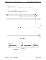
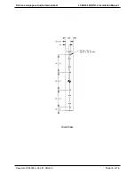
3.1.5 A shallow mounting depth makes this monitor ideal for bulkhead
use. Convenient mounting holes are strategically located on the left
and right sides, as well as the back of the unit. The unit has eight
(8) 8-32 UNF-2B on the left and right sides, four (4) on each side.
The maximum depth should be no more than 0.50 inches. In
addition, the unit has eight (8) 8-32 UNF-2B on the back. The
maximum depth should be no more than 1 inch. Refer to Section
7.0, Reference Drawings, for mounting hole diameters and
configuration.
3.1.6 The monitor should be located as close to the source equipment as
possible in order to reduce the possibility of noise introduced into
the video. Refer to Section 6.0 for unit dimensions.
3.1.7 A grounding lug is included as part of the housing. See Section 7.0
for details.


