background image

189

Installation Guide

Selection Page

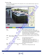
The Selection page allows access to various image and event playback functions.

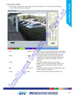
Red 

Play 

Switches the selected camera(s) shown on screen into 

Play mode.

Green 

Goto 

Opens the GoTo menu.

Yellow 

Event 

Displays the Events menu.

Blue 

Menu 

Opens the Configuration menu pages.

IMPORTANT:  Selecting this option will exit the Viewer menus. This will be logged in the User Activity 

Log as the current user terminating the session, refer to ‘Appendix C’ for further 

information regarding the User Activity Log.

Purple 

Next 

Opens the next page of the Viewer menu.

Intelligent Security & Fire Ltd

Summary of Contents for DV-IP NV4

Page 1: ...Installation Guide I n t e l l i g e n t S e c u r i t y F i r e L t d ...

Page 2: ... 97 Schedule 110 Alarm Settings 115 Network Settings 132 Features Text 149 Analytics Third Party IP Cameras 150 Installing An Advanced Feature License 151 Archive 170 Oracle Dome Configuration 172 Unit Operation 188 Operating the Viewer 189 Using the optional keyboards 213 Appendix A Closed IP Configuration Scenarios 217 Appendix B Pinouts 222 Appendix C Remote Control Codes 223 Appendix D User Ac...

Page 3: ...ecure answer to IP Video meaning that no prior knowledge of IP networking is required Sophisticated and Dependable network security can be achieved with a single click Leverage the powerful embedded NVR within the NV4 to incrementally grow your camera estate Combine your existing installed analogue cameras with secure IP and HD cameras from a Closed IPTV system Up to 32 camera streams can be conne...

Page 4: ...built in to ensure maximum compatibility with future developments in networked security NetVu Connected technology enables the Unit to fully interact with other NetVu Connected compatible products from Dedicated Micros including the DV IP Decoder NetVu ObserVer and PDA Viewers Providing interoperability between the worlds leading security companies NetVu Connected uses industry standard networking...

Page 5: ...cking an area of the monitor The camera will instantly respond positioning the selected area in the middle of the screen ideal for tracking movement through a scene MAP Users can now navigate around their CCTV installation using a graphical map Selecting the relevant camera from the map will instantly connect the user to that cameras image stream With the ability to load bespoke map images and flo...

Page 6: ...currence Regulatory Notes and FCC and DOC Information USA and Canadian Models Only Warning This equipment has been tested and found to comply with the limits for a Class A digital device pursuant to part 15 of the FCC rules These limits are designed to provide reasonable protection against harmful interference when the equipment is operated in a commercial environment This equipment generates uses...

Page 7: ...s an integrated CD R DVD R writer the following are additional warnings associated with installing and operating the CD R DVD R writer please pay particular attention to this information Caution Use of controls or adjustments or performance of procedures other than those specified herein may result in hazardous radiation exposure To prevent exposure to laser emanations harmful to the eyes do not a...

Page 8: ...to protect from overheating Ensure there is a 3cm gap on both sides of the unit Ensure the IR receiver on the front of the unit faces the operator position and is not more than 10 feet 3 metres from the operator An IR Remote Control Extender is also available Ensure the unit is not located anywhere it could be subject to mechanical shocks The unit should be located in an area with low humidity and...

Page 9: ... Various storage sizes are available dependent on the combination of the number of cameras the storage options and record rates selected MultiMode Recording The unit supports MultiMode recording which is a storage technology developed by Dedicated Micros This offers the ability to set different recording rates resolutions and compression formats across scheduled normal and alarm modes for each ind...

Page 10: ...Input model Video VID1 to VID16 75Ω BNC composite video input 1V pk pk with loop through 1V MON A 75Ω BNC composite monitor output 1V pk pk MON B Spot Monitor output HDMI 1 High Definition Multimedia Interface connector DVR Mode Spot Decoder mode Configurable Main HDMI 2 High Definition Multimedia Interface connector DVR Mode Main Decoder mode Configurable Main Audio AUX AUD IN x2 3 5mm phono sock...

Page 11: ...net Network KBD RJ12 connector for use with Dedicated Micros telemetry keyboards KBC1 KBC2 EXP RJ12 expansion port SATA 2x E Sata port available for storage expansion Alarms and relays ALARMS IN Via 25 way female D Type 24V 200mA 20 general alarm inputs Range of Alarm states are i 0 800R Short circuit ii 800R 2K closed contact iii 2k 12k open contact iv 12K open circuit RELAYS Via 9 way female D T...

Page 12: ... DHCP works by assigning an IP address at initial connection to the network It is possible however that this IP address can change without notification i e following power failure DNS Dynamic Name Service allows the unit to be assigned a meaningful name which can be used to reference the unit instead of an IP address This will remain constant in the event that the DHCP assigned IP address changes ...

Page 13: ...an available channel through the configuration pages The NV4 has 16 channels that can be used for analogue input Analogue channels can also be used as recode channels for 3rd party IP inputs or they can also be used to remote codec NetVu Connected capable encoders The available inputs are Analogue Recode IP NetVu Connected 3rdParty NV4 8ch 8 or 8 or 32 NetVu connections NV4 8ch 8 or 8 and 24 NetVu...

Page 14: ... phono sockets AUDIO IN and AUDIO OUT The audio channel defaults to recording camera 1 The following modes of operation are supported Challenge intruders from an RVRC Listen to local audio from a site at the RVRC Record local audio from a site with the video Replay all audio through a local Audio output not supported when Audio out is used as a challenge PA source Note The Audio output can be conf...

Page 15: ... Pin 15 DTX Pin 24 Earth Pin 22 Earth Pin 20 DTX Pin 18 DTX Pin 16 DTX Pin 14 DTX IR ALARMS The NV4 supports 20 normally open closed tamper proof alarm inputs or one Global keyswitch input with camera specific inputs configurable as entry exit alarms The alarms support tamper proof detection using 1k in line and 5K end of line resistance The unit detects short circuit open circuit and contact clos...

Page 16: ... ohms 1K 5 6K Closed the resistive value is 1K ohms as the circuit does not see the 5 6K ohm resistor Open Circuit Tamper the resistive value is infinity as the circuit has been cut and therefore is open Short Circuit Tamper the resistive value is 0 Ohms Step 7 Connecting Serial Ports Serial ports have three main uses 1 Connecting twisted pair telemetry for PTZ cameras 2 Providing text data record...

Page 17: ...ess Eth B setting Closed IPTV Settings must be enabled if using Oracle IP domes in a Closed IPTV environment A DM Oracle 2040 or 2060 Dome can be connected via either co axial telemetry or RS485 twisted pair If using co axial the address switches should be set as Blue switch F Yellow switch D If the dome is being connected using RS485 the dome address should be set according to the camera number o...

Page 18: ... B VID 16 B A B The NV4 has an internal power supply unit Connect the mains lead to the unit and then to the wall socket or to a fused spur connection To be compliant with wiring regulations in some countries an Alarm Security device should be connected to a fused spur and not a wall outlet socket check local regulations before installation I n t e l l i g e n t S e c u r i t y F i r e L t d ...

Page 19: ...unters a channel that does not have Port Free status then the video source will be added to the un allocated list consecutive cameras will only be applied to channels that are Port Free For example the Layer 3 Enhanced CCTV Switch has channel ports 1 3 4 listed as Port Free 2 is an Analogue camera If one 4 channel ICR encoder is added to camera 1 The result is ICR Encoder Camera 1 Camera 1 NVR ICR...

Page 20: ...d Single IP assigned Multiple IP connection Unknown IP detected Analogue channels take precedence If an analogue camera is present and connected then it will only become Port Free if the channel is set to Not Connected on the Closed IP NVR configuration pages The de allocated cameras are added to the Camera Unallocated Cameras page on the NVR which shows a tabulated list of all unallocated cameras...

Page 21: ... Note If a DNS Domain Name Server address is not to be used it is strongly advised that a fixed IP address be assigned a DHCP assigned address can change without notification i e following power failure A fixed IP address can be assigned via the Network Settings Network menu For information on locating the unit s IP address via a PC and serial port connection refer to Appendix D Default DNS Addres...

Page 22: ...PTV It is only possible to change Closed IPTV settings when the system is in Configuration mode Closed IPTV Settings The Closed IPTV logo in the top corner of the configuration pages gives a quick indication of whether the system is in Secure or Configuration mode Dedicated Micros recommend the system is always left in Secure Mode unless Closed IPTV settings are actually being edited Secure Mode C...

Page 23: ...ation Toggle the speed of PTZ camera movement two speeds available Use the Zoom button to zoom in out with a selected camera Also used to zoom x2 into Live or Playback images This button will change the Zoom Keys operation to focus or iris functions when available Use this button to cycle through available cameras This button should be pressed followed by a numeric entry to carry out auxiliary act...

Page 24: ...Green Yellow Purple to directly access the corresponding function displayed on the menu screen The Number pad should be used to select specific cameras and preset positions when available Use the Playback buttons to interrogate recorded images Use the LIVE button to switch from Playback or menus to a LIVE display I n t e l l i g e n t S e c u r i t y F i r e L t d ...

Page 25: ...isplayed if Enable Event Search is selected in the Features menu System Settings Features Select the Viewer menu tab to access the unit s Viewer function refer to Unit Operation for information on the numerous Viewer features Select the Download menu tab to access the various Download sub options Select from Product Manual Select to open an electronic version of the Installation Operation Guide Ob...

Page 26: ...ly IMPORTANT By default no Usernames and Passwords are required to access any of the various menus Usernames and Passwords can however be added to regulate access to the Configuration and Viewer menus Refer to the Console Settings User Accounts menu for information on establishing Usernames and Passwords I n t e l l i g e n t S e c u r i t y F i r e L t d ...

Page 27: ...oftkey options shown at the base of each menu The options available will depend on the menu being viewed Select a softkey option by pressing either the corresponding button on the IR Remote Control if viewing the menus locally or by selecting the relevant option via the PC mouse if viewing the webpages Note Any changes made via the webpages are automatically saved when the page is closed To manual...

Page 28: ...n either upper or lower case format by multi tapping a relevant button For example with the cursor located in the text entry window of the Virtual Keyboard repeatedly tap button 2 to cycle through the following characters 2 A a B b C c 2 etc To select one of these characters simply stop tapping the button when the chosen character is displayed The cursor will then progress ready for the next chara...

Page 29: ... allows the unit time and date settings to be adjusted including setting the timezone The Serial Ports page allows each of the four serial ports to be individually configured for one of a range of operations including EPOS debug PPP and telemetry The Audio page shows the settings available for each of the audio channels and allows configuration of audio quality The Features page allows control of ...

Page 30: ...his is displayed when the unit is accessed via NetVu ObserVer and is sent when transmitting information to a Remote Video Response Centres RVRC Video Standard Displays the video standard adopted by the unit i e PAL NTSC Number of Cameras Shows the number of camera channels on the unit Global PPS Details the Global PPS Pictures Per Second recording rate for all cameras at 4CIF 2CIF and CIF Video St...

Page 31: ...ore Revision This identifies the Framestore Revision the unit is running PC Apps Revision This identifies the revision archive of the Viewer and associated PC Apps software Boot Software Rev Displays the infrastructure componentry software revision Help Videos Rev This identifies the version of Help Videos installed on the unit Note Refer to Go To Viewer Help Videos for guidance on viewing the emb...

Page 32: ...m Red Select this option to return to the System menu About Blue Select to open the Status About page Refresh Purple Refreshes the information on the current page I n t e l l i g e n t S e c u r i t y F i r e L t d ...

Page 33: ... Restart reason The reason for the last restart is displayed Codec Up to four codecs are installed within the unit dependent on model Cameras are assigned to the codec in the following sequence Camera 1 is assigned to Codec 1 Camera 2 to Codec 2 Camera 3 to Codec 3 Camera 4 to Codec 4 Camera 5 to Codec 1 Camera 6 to Codec 2 etc Within each Codec window each camera channel is listed along with conn...

Page 34: ... to be functioning correctly will be highlighted light green Those deemed to have failed will appear red Camera channels with no connected camera will appear dark green Alarm Status Yellow Select to open to the Status Alarm page Rem Codec Blue Select to open to the Remote Codec Status page Refresh Purple Refreshes the information on the current page I n t e l l i g e n t S e c u r i t y F i r e L ...

Page 35: ...s Alarm Contacts Zones Relay Outputs Alarm Contacts Alarm Zones and Relay Outputs that are in an active state are shown light green In active ones appear dark green not illuminated Alarms Blue Select to open to the Alarm Inputs page Refresh Purple Refreshes the information on the current page I n t e l l i g e n t S e c u r i t y F i r e L t d ...

Page 36: ...icon to view the relevant pages refer to Appendix J Status Pages for a description of each page System Information Select to open to the System Attributes page Software Revisions Select to open to the System Settings System Software page I n t e l l i g e n t S e c u r i t y F i r e L t d ...

Page 37: ...the unit can be accessed from this page Selected logs are displayed on the page below About Blue Select to open the System Status About page Refresh Purple Refreshes the information on the current page I n t e l l i g e n t S e c u r i t y F i r e L t d ...

Page 38: ...t Red Select to reset the unit Note The unit MUST be reset to implement system language changes refer to System Settings Maintain for guidance on resetting the unit Session Language Select to change the language settings for the current session only Choose Select to immediately activate session language changes Reset Red Select to reset the unit Refresh Purple Refreshes the information on the curr...

Page 39: ...also be displayed as mm dd yy or yy mm dd Set Time Enter a current time for the unit Set Date Enter a current date for the unit Set Time Green When current time date as been entered select this button to implement changes Time Zone Select the relevant timezone offset from the accompanying drop down menu SNTP Server A Simple Network Time Protocol SNTP server allows external devices to connect and s...

Page 40: ...webpages Note The PC Time and Sync Time options will only be available if viewing the menu via the webpages Reset Red Select to reset the unit Set Time Green When current time date as been entered select this button to implement changes System Yellow Select to open the System Attributes page Sync Time Blue Use this button to synchronise the time of the unit to that of the PC being used to view the...

Page 41: ... port for Telemetry purposes Comm Sets port for Comms purposes EPOS Sets the serial port for connection to an EPOS Electronic Point Of Sale device Note It is recommended that Serial port 1 be set for Debug operations Interface Type Choose the type of serial interface being used Select from RS232 RS485 or RS422 Baud Parity Data Stop Flow Control These options allow the Serial port communication set...

Page 42: ...tion This page allows configuration of some features on cameras connected to the unit Update local sys config on save Select to update and enforce any changes made here in the local system display Camera Nuisance Count This is a repetitive detector value When a camera failure alarm is received on the unit it will store the alarm time and monitor the number of times the same alarm is triggered with...

Page 43: ...Codec is used for NetVu Connected video sources IP Camera is used for all NetVu Connected cameras and 3rd party units Fail Rep Select this option to activate a Failure report in the event of camera connection failure video loss Cam Setup Red Select to open the Camera Setup page Serial Blue Select to open the System Serial page Refresh Purple Refreshes the information on the current page I n t e l ...

Page 44: ...en Enabled will result in all audio received by the unit being recorded to the HDD Record Audio Challenge Select this option to record an audio challenge received via an IP connection i e originating from a remote client Record Gain This option allows the Record Gain level to be set This is the base setting from which the AGC Automatic Gain Control will operate Select from 1 to 15 The default and ...

Page 45: ...45 Installation Guide Reset Red Select to reset the unit Refresh Purple Refreshes the information on the current page I n t e l l i g e n t S e c u r i t y F i r e L t d ...

Page 46: ...e information Note When de selected here the Text in Image menu will no longer be displayed in the menu tree Email Reporting Select this option to activate the Email Reporting function refer to Network Email for more information Note When de selected here the Email Reporting menu will no longer be displayed in the menu tree Keyboard Enable 485 bus Select this option to enable the Keyboard 485 Bus ...

Page 47: ...Server Name is unique within the workgroup being used To access the unit via a PC running SMB and having access to the same Workgroup open My Network Places Entire Network Microsoft Windows Network The Workgroup containing the unit and PC s should then be available Files and folders can then be copied added as required Note Use the 10 100Mbps network option Net 2 for SMB purposes the unique Server...

Page 48: ...ort Selection Select Automatic to enable the unit to select a suitable port for telemetry purposes Select Default to use the default port settings 1025 Select User Defined to use settings entered in the Telemetry Port option Samba Workgroup Enter the name of the Samba workgroup to enable sharing of files and directories to from the unit To access the unit via a PC running SMB and has access to the...

Page 49: ...256 should only be changed under expert advise TCP Reassembly Queue Limit This setting limits the maximum number of TCP segments allowed in the reassembly queue Preventing the construction of highly segmented data helps protect against a common DoS Denial of Service attack Remote Codec Default ConnectionThis selects the initial connection type to use for an auto configured remote codec camera sele...

Page 50: ...er function Comb Filter can help improve the fine details of a video signal image by filtering the luminance and chrominance separation process Disable Transcoding Select to disable the unit s transcoding capabilities In normal circumstances this should always remain enabled 3D Input Filter Advanced input filtering to the video codec providing input signal noise reduction It s primary purpose is t...

Page 51: ...onsequently some of the image at the top and bottom of the frame may be cropped Frame Fit forces the frame to fill the available segment proportionally resulting in black bars left and right on some multi display choices Note There is no cropping or distortion on the recorded image these settings are for display only System Red Select to open the System Features System page Network Green Select to...

Page 52: ...ch for further details Enable RVRC page Select this option to activate the RVRC Remote Set Unset Override function refer to Record Settings RVRC for more information Note When de selected here the RVRC menu will no longer be displayed in the menu tree System Red Select to open the System Features System page Network Green Select to open the System Features Network page Video Yellow Select to open ...

Page 53: ...d the to from box Select to save the selected settings to the selected media Restore Blue This button uses the select box and the to from box Select to save the selected settings to the selected media Note Selecting the Restore button will cause the system to reboot select Select which files will be saved or restored To From Select the relevant media device to save to or restore from i e USB or CD...

Page 54: ... Default button will cause the system to reboot Reset Red Select to reset the unit Default Green Select to return the unit to its factory default settings Export Logs Yellow Select to export all Logged data to a connected external device Restore Blue Select to restore previously saved settings from the selected media Save Purple Select to save current unit settings to the selected media I n t e l ...

Page 55: ...hanges this page will alter the Default C file If you already have a custom PowerScript on your unit which uses Default C please contact Dedicated Micros Technical Support for guidance Tel 44 0 845 600 9502 for further guidance Reset Red Select to cycle the power to the unit Save Green Updates the DEFAULT C file on the NVR to enable selected scripts on reboot Refresh Purple Refreshes the informati...

Page 56: ...whilst also giving an overview of the port status of each connected switch The Discover page allows automatic discovery of Layer 3 Enhanced CCTV Switches connected to the Closed IPTV NVR The Upgrade Switch page allows connected Layer 3 Enhanced CCTV Switches to be quickly easily and securely upgraded The Advanced page allows switch base camera numbers to be set and camera details to be synchronise...

Page 57: ... a combination of this rotary dial and the Base Camera setting on the Closed IPTV settings menu Layer3 Enhanced CCTV Switch Layer3 Enhanced CCTV Switch Layer3 Enhanced CCTV Switch Layer3 Enhanced CCTV Switch KBD USB ETH 0 AUX AUD1 IN VID 1 MON B VID 2 VID 3 SATA1 OUT A VID 8 VID 6 VID 4 VID 5 VID 7 ALARMS RELAYS SERIAL 1 SERIAL 2 SERIAL 3 PTZ SERIAL 4 PTZ AUX AUD2 IN OUT EXP O I IR SATA2 ETH 1 HDM...

Page 58: ... connected device is not recognised IP Detected Magenta A port which has detected a network connection but the device is either not assigned to current channel or is assigned elsewhere Security Level Select from Configuration Mode or Secure Mode In Configuration mode The security settings of all cascaded Layer 3 Enhanced CCTV Switches can be globally edited The configuration of all endpoints video...

Page 59: ... can be compromised if left unrestricted Additional Closed IPTV systems should always be added in Config mode to allow auto IP configuration to accommodate existing systems and avoid ip conflicts Restrict multicast from general network This disables client network access to the multicast services on the camera but does not disable standard web access for camera configuration etc unless Restrict pu...

Page 60: ...ork Reconnect after Reconnection to the network will be attempted after a security breach once this period has elapsed If the security breach is detected again connection to the public network will remain blocked Isolate from Closed IP If a security breach is detected the video source is isolated from the Closed IPTV network Generate system event Select this option to report port violation as syst...

Page 61: ...nf uses industry standard IP protocols to allow devices to automatically discover each other without the need to enter IP addresses or configure DNS servers Variable The parameter being passed by the discovered switch There is the capability to show 16 switches each switch detail is separated by a comma Value Details the appropriate port variable value CIP Settings Red Select to open the Closed IP...

Page 62: ...to be upgraded and press the Upgrade button The NVR sends the required file to the switch and automatically restarts it Upgrade Switch Use the drop down to select the switch to be upgraded or upgrade all switches using the All Switches option Progress The entry shows the status of the switch upgrade CIP Settings Red Select to open the Closed IPTV Settings page Upgrade Yellow Begins the forced upgr...

Page 63: ...cur for Remote Codec cameras ie NetVu Connected cameras video servers and only in configuration mode Switch Displays the switches that have been found and accepted by the NVR refer to Discover Base Camera Each switch can have up to 16 video sources attached to it A switch may not have all ports configured with a video source so there may be more than two switches attached to the NVR This option se...

Page 64: ...xample Settings Scenario 1 One switch 16 Analogue cameras attached to NV4 CIP Switch Hardware Setting No of Cameras Base Camera Camera numbers 0 16 17 17 32 Scenario 2 Two switches 0 Analogue cameras attached to NV4 CIP Switch Hardware Setting No of Cameras Base Camera Camera numbers 0 16 1 1 16 1 16 17 17 32 Scenario 3 Two switches 8 Analog Cameras ports 7 16 Switch Hardware Setting No of Cameras...

Page 65: ...an IP connection The Remote Monitors page allows monitors not physically connected to the unit to view camera images received by the unit The Viewer Defaults page allows the Viewer menu settings to be configured The Display page controls how the local monitors present information They control whether text will be displayed on the Main or Spot monitors the colour of that text and how long cameras b...

Page 66: ...eras as shown below Server URL Server Name Camera Selection localhost local 1 4 1 8 or 1 16 System Select from 20 available systems using the drop down menu System Name If required enter a recognisable name for the system this name is held on the NVR and represents the system Server URL Enter the IP addresses of the servers providing the video signals Server Name Enter a name for the accompanying ...

Page 67: ...Server URL to automatically populate the system with the server name and ALL available cameras from that server Save Grey Select to save current unit settings Refresh Purple Refreshes the information on the current page I n t e l l i g e n t S e c u r i t y F i r e L t d ...

Page 68: ...ated in each system i e to access Camera 1 in System 1 first select System 1 via the System Selection map then select Camera 1 Remote Cam Num Identifies the number the camera is allocated on its server Selecting this number via the Viewer menus will not result in images from that camera being displayed Server URL Displays the URL of the server supplying the video images Server Name Displays the na...

Page 69: ...s of the server connected to the monitor or video wall is required Cameras can then be selected via the remote monitor Up to 32 remote monitors or video walls can be configured Enter the IP address of the server connected to the monitor Save Purple Select to save current unit settings to the selected media I n t e l l i g e n t S e c u r i t y F i r e L t d ...

Page 70: ...tion POWER HDD NETWORK POWER HDD NETWORK U1 U2 M2 M1 To view the cameras connected to U1 on a monitor connected to U2 Enter the IP address of U2 into the Remote Monitor page on U1 I n t e l l i g e n t S e c u r i t y F i r e L t d ...

Page 71: ...d for images that need to travel over a network JPEG requires a higher bandwidth and should be reserved for higher capacity networks and local viewing only Default Full Req Images displayed full screen in the Viewer menus can be shown in either High Medium or Low resolution Default Quad Req Images displayed in Quad format in the Viewer menus can be displayed in either High Medium or Low resolution...

Page 72: ...ws cameras to be accessed and controlled via the Viewer menu In Decoder Mode connected cameras can be accessed viewed or controlled via Dedicated Micros Pick a Point system Note For further information regarding Dedicated Micros Pick a Point system please contact Dedicated Micros customer services in your region Mouse Sensitivity The sensitivity settings of the mouse can be adjusted from the least...

Page 73: ...d Select to reset the unit and implement any changes made to the Video Output mode or Applet Location fields Save Purple Select to save current unit settings to the selected media I n t e l l i g e n t S e c u r i t y F i r e L t d ...

Page 74: ...the displayed text can be changed Select from the options available in the drop down list Sequence Dwell The sequence dwell time can be set from 5 to 99 seconds The dwell time is the period a camera s images are displayed before switching to the next camera in the sequence Sequence main on startup Select to sequence live views from all connected cameras on the main monitor upon system start up Sof...

Page 75: ...out can include any camera in any available segment Camera selection switches to full screen Select to auto switch to full screen mode any camera channel selected from multi display selected via the Viewer feature Select All Blue Select to add all available cameras to the Spot Monitor Sequence Refresh Purple Refreshes the information on the current page I n t e l l i g e n t S e c u r i t y F i r ...

Page 76: ...l display all available numbered systems Selecting a hotspot then opens the relevant System camera map Graphic Location Enter the location of the relevant map graphic including the full I P address of the server holding the map The map image will be displayed if linking is successful The linked map can be in gif or jpeg format and should not exceed 500 by 350 pixels Map Screen Offset These co ordi...

Page 77: ...ted Micros Oracle Dome camera Clicking the hotspot will send the Oracle Dome camera to a pre determined view absolute positioning However if the dead centre of the hotspot is selected the camera will be viewed from its current location The absolute positioning point will depend on the data entered here A setting of 0 would result in the camera facing its Original base position To change the preset...

Page 78: ...opy all text displayed in the Map Data text window then save this data as a text file To import data copy relevant text from an external location and paste into the Map Data text window When the menu is exited this data will be used as the Map Config settings Note Dedicated Micros recommend the existing Map Data is saved before import Map Config Blue Select to open the Display Map Config page Refr...

Page 79: ...t access to the Video FTP archiving feature used with NetVu ObserVer Telnet Assigning username and password requirements for Telnet connections will limit Telnet access to the unit Telnet can be used to upgrade the unit Serial Assigning username and password requirements for Serial connections will limit access via a Serial link Menu Configuration Assigning Menu Configuration access privileges wil...

Page 80: ...ntered access will be allowed to all connected cameras in both live and playback modes Note There are no default usernames and passwords for any of the Account Types If none are assigned access will be granted to all users and no request for a username and password will be made Account List When an Account Type is highlighted details of users with access will be displayed Add Highlight an administ...

Page 81: ...from a network based source i e IP Server These streams are configured on the remote device This feature is predominately intended for use with 3rd party IP camera streams connected via the 3rd party IP camera unlock feature The Intelligent PTZ menu details the Dedicated Micros Oracle Domes connected to the Closed IPTV System The Unallocated Cams menu details the cameras that are available to the ...

Page 82: ... camera channel for review and adjustment Camera Nuisance Count This is a repetitive detector value When a camera failure alarm is received on the unit it will store the alarm time and monitor the number of times the same alarm is triggered within an hour period If the detector is triggered the number of times entered here the unit will set the camera to No Connection To disable this feature leave...

Page 83: ... to Appendix I for details of supported telemetry protocols Note A serial port should be assigned if a serial protocol is used Default to preset If a telemetry camera has been assigned a preset position select the chosen preset position here Enter the time period in minutes of inactivity which will result in the camera moving to its preset position refer to Viewer menus Program Page for guidance o...

Page 84: ...cros IP Mode Select the IP mode used to receive incoming IP data Select from Simple Stream Received IP streams are non compressed and are viewed as configured on the originating source Recode Stream When selected the unit will recompress the incoming IP stream to the record profile settings established for this camera channel in the Profile Record menu Record Settings Profile Record This feature i...

Page 85: ...e any NetVu connected cameras will be applied above local camera level When Simple Stream and Recode Stream are selected via IP Mode the following options will be available IP Address Enter the URL address of the image source Note Typically this data will be automatically added Channel If the URL is a multichannel device e g DV IP NV1 this specifies which channel to use Both types Live Trans Red S...

Page 86: ...e and normal lens types Pitch Allows the image to be rotated counterclockwise by ninety degrees Ratio H Allows the horizontal ratio of a panamorphic lens to be set Ratio V Allows the vertical ratio of a panamorphic lens to be set Ratio x100 Allows the multiplier ratio of a panamorphic lens to be set Cam Setup Red Select to open the Camera Setup page Cam Overview Green Select to open the Camera Ove...

Page 87: ...ick on Local Camera Setup to edit the settings held in the DV IP NV8 Click on Setup to open the Setup menu on the connected video source CIP Settings Red Select to open the Closed IPTV Settings page Unalloc Green Select to open the Camera Unallocated Cams page Refresh Purple Refreshes the information on the current page I n t e l l i g e n t S e c u r i t y F i r e L t d ...

Page 88: ...o the NVR and select the cameras to be upgraded via the interface pages The Upgrade button will then send the updated files to the selected camera Select All Red Select all displayed cameras Deselect All Green De select all displayed cameras Upgrade Yellow Upgrade the selected cameras Refresh Purple Refreshes the information on the current page I n t e l l i g e n t S e c u r i t y F i r e L t d ...

Page 89: ... Only those cameras designated as IP in the Camera Setup menu will be available Configuration menu Camera Setup Copy to all Select this option to apply current settings to all connected cameras The following options can be configured for Set Unset and Override record profiles when operating under Normal non Event conditions refer to Configuration Menu Record Settings Profile Record for information...

Page 90: ...ecompress the incoming IP stream to the record profile settings established for this camera channel in the Profile Record menu Record Settings Profile Record This feature is only accessible with 3rd party IP camera when the 3rd party IP camera license has been enabled Remote codec When selected the unit will utilise the codec in the remote NetVu connected video server camera as if it was directly ...

Page 91: ...rt If required edit the port input data This will default to 80 HTTP Chan If required edit the channel input data PPS Edit the PPS Pictures per Second recording settings Recode Select to activate the recode option When Remote Codec is selected via IP Mode the following options will be available IP Address Enter the URL address of the image source Channel If required edit the channel input data IP ...

Page 92: ...vailable through the NVR s menus Note The setting Restrict public access Eth B must be enabled on Closed IPTV Settings if using Oracle IP domes in a Closed IPTV environment These pages are all documented in the manuals that accompany the Oracle Dome also refer to Appendix H Oracle Dome Configuration The Oracle Dome manual can also be downloaded from the Dedicated Micros website I n t e l l i g e n...

Page 93: ...ped onto this list Cameras can then be assigned to a free channel or dismissed as no longer required A dismissed camera can be added back into the un allocated list by refreshing the connection unplugging it from the switch and plugging it back in again Assign to Displays all available unassigned camera positions Assign Assigns the associated IP stream to the selected camera Remove Entry Deletes t...

Page 94: ...s implemented The viewing software is commanded not to display the privacy zone segment The images are still recorded however It is the responsibility of the user to ensure all viewing applications support the privacy zone feature i e the viewer must be able to read the meta data in the image header and suppress displaying the created privacy zone How to configure a Privacy Zone Use the mouse eith...

Page 95: ...r or Embedded Console feature will have the Privacy Zone applied to them This setting can disable the Privacy Zone from live images viewed on Embedded Consoles and Remote Monitoring servers Suppress Network Replay Images served by this unit to a second NVR using the Remote Monitor or Embedded Console feature will have the Privacy Zone applied to them This setting can disable the privacy zone featu...

Page 96: ...e using these options The JPEG Trigger page allows configuration of the pre trigger feature for cameras recording JPEG mode only When enabled the pre trigger feature will buffer and store alarm recording prior to an event trigger The Holiday and Weekend page enables Set mode to be activated for individual dates i e public holidays or weekends The Protect Video page allows previously recorded data ...

Page 97: ...ays the record duration possible using the current configuration Timed Expiry Days Images recorded onto disk can be programmed to expire after a user defined number of days This option is useful if you are required to adhere to legislation on maximum recording time Warning Once the timed expiry has been set all images older than the selected time will be lost Default All Green This button sets all...

Page 98: ... mode Turbo mode allows video images from any analogue camera or 3rd Party IP recoded camera to be recorded and streamed at the maximum possible rate without the need to configure individual settings Turbo mode must be set Globally and will result in MPEG record rates of 12 5pps 4CIF and 25pps 2CIF CIF QCIF Note When Turbo Mode is selected there will be only ONE configurable Record Profile across ...

Page 99: ...c Loading Days Recording Displays the record duration possible using the current configuration Channel Enables selection of a specific camera for editing Copy To End Select to copy the current profile record settings to all camera channels Copy To Next Select to copy the current profile record settings to the next camera channel Filter by Connected cameras are available to be sorted by resolution ...

Page 100: ...gnisable titles i e Day Night Weekend via the Schedule menu Record Settings Schedule Comp Select image compression format MPEG H264 JPEG PPS The accompanying dropdown list allows the number of frames captured per second to be set The pictures per second pps option allows either 6 5 2 1 0 5 0 25 or 0 1 pps to be recorded Pictures can also be recorded at Real Time speed 3 4 Real Time or 1 2 Real Tim...

Page 101: ... is currently in turbo mode and the currently configured record settings do not warrant turbo mode a message will be displayed informing the user that At the current settings the unit does not need to be in turbo mode The codec s performance thresholds are detailed in the About Codec Loading menu System Settings Status About Codec Loading Days Recording Displays the record duration possible using ...

Page 102: ...kend via the Schedule menu Record Settings Schedule Comp Select image compression format MPEG H264 JPEG Res Select image resolution QCIF CIF 2CIF or 4CIF Rate_kbps If MPEG4 is selected the figure entered here will be the bit rate allocated A higher bit rate will provide better quality MPEG bit rates can be entered within the range of 45 2500K bits second IMPORTANT The bit rate allocation here will...

Page 103: ...vailable memory dependent on other cameras requirements of the buffer space Select Enable to activate Pre Trigger Duration secs The Pre Trigger Duration is the length of recording prior to an event trigger that will be saved with the event recording Note It is recommended that the Pre Alarm sec option in the Alarm Zone Input menu be set to the same value as the Pre Trigger setting This will ensure...

Page 104: ... been protected unprotected Start Date Enter a start date to protect video Start Time Enter a start time to protect video End Date Enter an end date to protect video End Time Enter an end time to protect video Protect Length days Enter the number of days that selected files will be protected for Protect Select this option to protect recorded video for the selected time period s Unprotect Select th...

Page 105: ...h within the protected video list to conclude at a specific Time and Date Unprot all Red Select to unprotect all recorded video from the list Protect Green Select to protect recorded video for the chosen time period Unprotect Yellow Select to unprotect recorded video for the chosen time period Refresh Purple Refreshes the information on the current page I n t e l l i g e n t S e c u r i t y F i r ...

Page 106: ...ngs Video Storage 2 Plug a USB storage device into one of the available USB ports and click the purple Refresh button The newly connected device will be displayed with a udd prefix The SD card if installed will also be displayed and can be allocated in the same way USB devices will be prefixed udd 3 The device may require formatting DM recommends the device is formatted even if it was previously b...

Page 107: ...tion about the allocation process The unit will require a Reset once allocation is complete Note The unit application drive is protected if it is allocated the unit will only remove the video folder Formatting any other device will remove all data In either case recording on the system is halted while formatting and if already allocated the formatted device will be de allocated as a video storage ...

Page 108: ... system Once the power has cycled the system will build the required PAR files ready for recording to commence progress will be displayed in the Feedback column Note There will be a pause before recording begins dependant on the size of the USB device as video partitions are built I n t e l l i g e n t S e c u r i t y F i r e L t d ...

Page 109: ...cording qualities and rates under normal and alarm conditions for a high degree of control in a range of situations The Setup page allows configuration of the schedule including naming the modes of operation and controlling when the unit changes between modes The RVRC page allows a user to temporarily switch the unit s system state into set unset override mode The Holiday Weekend menu allows the u...

Page 110: ...erride mode Note Any changes to Mode titles here will affect the mode names displayed in the Profile Record IP Record and Zone Input menu pages Current Mode Shows the current timer mode according to the names entered in the Mode Title text boxes Day Time Enter the time using the 24hr clock when Unset mode will begin Night TIme Enter the time using the 24hr clock when Set mode will begin Keyswitch ...

Page 111: ...iles SET UNSET If these names have been changed on the Schedule page these menu options will display the user configured names UNSET Time Specifies what time in format HH MM the UNSET recording settings configured on the Profile Recording page will become operational SET Time Specifies what time in format HH MM the SET recording settings configured on the Profile Recording page will become operati...

Page 112: ... be displayed This will be logged with any override action Current system state The current system state will be displayed i e Set Unset Override Note The system state names displayed here will depend on those entered via the Schedule menu Record Settings Schedule Override duration minutes Enter a time period for the override procedure After this time period the system state will return to that co...

Page 113: ...nu Holidays Enter a date and press the Add button The date will be added to the Holiday list To delete highlight and select Delete Weekends Select Enable to activate the Weekend function Set mode will now be active for the dates outlined below Start Select a Start day and time for Weekend mode End Select an End day and time for Weekend mode Note Override mode will remain active until weekend is di...

Page 114: ...Viewer menu The Masked Camera Det ection page allows cameras to be enabled for masked detection based on a threshold contact value and dwell time The VMD Act ivity Response page enables configuration of responses following an VMD Activity Detection trigger The Activity page allowed activation and configuration of the Activity feature on all video inputs The Activity feature enables cameras to auto...

Page 115: ...odule to configure N_O Normally Open Contact N_O indicates the non alarm state of the input Tick the N_O checkbox to set the corresponding input to Normally Open The alarm will then trigger when the input is closed shorted If left as Normally Closed the default setting the alarm will trigger when the input is opened Note If EOL alarms are to be used this option should not be selected i e leave set...

Page 116: ...ed during this period If it is again triggered more than the amount set in the nuisance counter it will remain de activated for another hour This will continue until the trigger value falls below the nuisance count setting To disable this feature leave the setting as 0 Stuck Time min If any of the alarms detectors are active for a period longer than specified here they will automatically be omitte...

Page 117: ...eriod the alarm will be triggered Zone An alarm zone can be established to logically group alarms and initiate actions when an alarm is activated There are 32 configurable zones Title This information is stored along with the relevant images in the database ensure this has relevance to the alarm zone Pre Alarm sec This is the time period prior to the start of the alarm included with the alarm reco...

Page 118: ...ute during the countdown will result in the alarm being triggered immediately This allows staff entry without triggering an alarm prior to switching the system to Set mode Exit Route Zone This creates deferred alarms along a specified route while the Exit timer is active This is in compliance with BS8418 the British Standard for remote video reporting centres Diverting from the exit route during t...

Page 119: ...e primary camera will be displayed when an alarm in this zone is triggered Create Database Entry An alarm activation will be added to the database The zone title will be used as part of the entry information Alarm Relay Select to trigger an alarm relay following zone activation Select the specific relay via the Relay option Profile Change Select to enable the unit to switch from Normal to Event re...

Page 120: ...in closed Alarm Image Snapshot Delay This figure allows a delay to be introduced before an alarm snapshot is taken This is used when the alarm relates to a PTZ camera which has to travel to a preset position Play Audio Message Following a Zone alarm trigger a specific audio message can be played IMPORTANT Audio messages must be uploaded to the unit in mono 8k wav format only The following naming c...

Page 121: ...eras to the zone These cameras will become part of the alarm sequence shown in the Viewer menus when the alarm zone is triggered Zone Act Yellow Select to open the Alarm Zone Actions menu Relays Blue Select to open the Alarm Global Actions menu Refresh Purple Refreshes the information on the current page I n t e l l i g e n t S e c u r i t y F i r e L t d ...

Page 122: ...e delay the unit will wait before declaring the camera is masked Threshold Defines the threshold the system uses to define that a camera is masked It will be necessary to adjust this figure to avoid false alarms Note In low light conditions enter a figure below the contrast threshold see below Experiment with camera masking alarm activation until a figure is found that avoids false alarms Contrast...

Page 123: ...he Zone trigger that will be activated when the view is masked On Clear Defines the Zone trigger that will be activated when the view is unmasked Refresh Purple Refreshes the information on the current page I n t e l l i g e n t S e c u r i t y F i r e L t d ...

Page 124: ...ction settings to the camera select None Note Whichever Detection option is selected here will result in the camera channel being only available for editing in the relevant configuration menu i e if Activity is selected for Channel 1 this channel can only be edited for Detection in the Activity Setup menu and not the VMD Configuration menu Activity To Trigger Following Activity activation select S...

Page 125: ...elay Select to trigger an alarm relay following zone activation Select the specific relay via the Relay option Email Image If this option is selected a JPEG will be added to the reporting email if Email Reporting is selected Enable in Unset This will enable Activity Detection when the unit is in Unset operation mode Enable in Set This will enable Activity Detection when the unit is in Set operatio...

Page 126: ...ivity activation specifically in relation to a PTZ camera Selecting Active while at Preset 1 will result in Activity mode functioning only when the camera is at preset position 1 Select Active while camera not in motion for Activity mode to function only when the camera is still Select Always Active for Activity mode to be in constant operation Activity Channel This is a drop down list of the vide...

Page 127: ...ng via the webpages use the mouse to navigate across the image use the left mouse button to place a cell Click on an active cell to deactivate it Reload Img Red This option will update the still image displayed in the Grid Editor Set All Green This option will insert a default square of 16 x 16 cells across the displayed video image Clear All Yellow This option will clear all entered cells Refresh...

Page 128: ...be accessed and configured remotely via the webpages Camera This is a drop down list of the video inputs on the unit selecting one of the inputs will display the corresponding video source Ensure this corresponds with the selected Channel Zone There are 16 VMD zones within the image that can be individually configured select the zone from the drop down list A selected zone can be re sized by click...

Page 129: ...e zone mode Pixel Count This value is set as a percentage and equates to the percentage of pixels in the selected zone that must change for the VMD event to be triggered The default setting is 20 Pixel Change This setting is a percentage value of the overall change required in the grayscale to be included in the pixel count The percentage change is defined over the complete range of black to white...

Page 130: ...s setting to make the unit return to the view displayed before the alarm activation once the alarm has ended Alarm Display Alert Enable this setting to display an alarm text alert in the colour specified in Alarm Colour in the Zone Actions Menu Normally Select whether the normal state of the relay contact should be Open or Closed for each of the local relays On Select to enable detection of the ac...

Page 131: ...his one as an IP source The Multicast page allows recordings from the unit s camera inputs to be forwarded to a port address enabling multiple viewers to view live data using a suitable media player without the need to directly connect to the unit The Email page allows configuration of the Email feature The unit can automatically transmit an email to an SMTP Server following an event i e on receip...

Page 132: ...ayed here Note If no IP address is set DHCP will automatically assign one The unit interrogates the network for a DHCP server which assigns an available IP address This IP address can change every time the unit is powered up Therefore it is recommended that DHCP be disabled by entering a suitable free static IP address Tip Use DHCP to locate a free IP address then fix the unit IP address to the fr...

Page 133: ...l wait before disconnecting the PPP Point to Point Protocol link if data has not been transmitted or received PPP Link Down Timer mins If for any reason the PPP connection is lost this is the time in minutes before the unit will be forced to drop the PPP connection Hangup After Alarm Select to close the network connection following transmission of alarm data Reset Red Select To Reset The Unit Rem ...

Page 134: ...the unit is located Gateway This is the IP address of the default gateway router DHCP The unit is set to default to DHCP The unit can be installed in a DHCP network environment where an IP address subnet mask and default gateway will automatically be allocated from the network DHCP Server It is recommended that this be disabled as the DHCP address is automatically allocated from a pool of availabl...

Page 135: ...es This is the maximum transmit unit for the Ethernet packet The MTU is the largest physical packet size measured in bytes that the network can transmit By default this figure is set to 1500bytes Reset Red Before any changes made to the Gb Network settings can take effect the unit must be reset Refresh Purple Refreshes the information on the current page I n t e l l i g e n t S e c u r i t y F i r...

Page 136: ...Record Note The Megapixel Resolution option will only be available if a megapixel camera is connected IMPORTANT There are three classifications of IP camera 1 Standard Resolution QCIF CIF 2CIF 4CIF 2 Standard Resolution VGA VGA SVGA QVGA Q2VGA 3 Megapixel VGA SVGA UXGA QVGA Q2VGA XGA XGA SXGA QXGA The classification of each connected camera channel can be viewed via the CamConfig menu System Setti...

Page 137: ...pend on the bandwith of the link increasing the pictures sent per millisecond may introduce time lag if bandwith is not sufficient On MPEG transmission increasing the pictures sent will also reduce the quality of the images as more images are transmitted for the defined bit rate MPEG Type Select whether transmitted MPEG4 images are sent as RAW data or in GOV Group of Video format RAW mode transmit...

Page 138: ...om www videolan org vlc download windows html Refer to Appendix E for guidance on configuring the Videolan VLC media player Note Multicast can only used for live viewing requests for stored images and events will still need to be made via the Viewer menu Multicast Address Assign a unique IP address This address is not assigned to any physical unit The VLC program will use this address when configu...

Page 139: ...This option can be configured to limit which users can access the images Check DMPLS for a new definition Enter one of the following numbers 0 restricts video to the same host 1 restricts video to the same subnet 32 restricts video to the same site 64 restricts video to the same region 128 restricts video to the same continent 255 is unrestricted in scopeRefresh Purple Refresh Purple Refreshes the...

Page 140: ...llocated a valid IP address Username Enter the login details for the email account used above Password Enter the login details for the email account used above Mail Server Address This is the IP address or URL of the SMTP Server that the email will be sent to The SMTP server will then forward this to the intended recipient Recipient Email This is the email address of the intended recipient Recipie...

Page 141: ...of the Activity Detection feature Send Image Select to send the image from configured primary camera associated with the triggering alarm Log Email Select this to add every email transaction that the unit issues to the email log Email Image Res Select the resolution settings for the image sent as an attachment in the Email Choose from Thumbnail LO low res MED medium res and HI high res Test Email ...

Page 142: ...alternative route can be identified via a secondary host If there is only one alarm receiving IP address you must enter the same details in both the primary and secondary connection settings Secondary Dial Profile It is possible to select a separate dial profile for the secondary host Public NAT Address This is the public IP or domain name for a unit connected to the Internet via a NAT Router or F...

Page 143: ...C prior to sending reporting data Alarm Responder Port This specifies the network port number used for reporting to the alarm server In normal circumstances this should be left at the default value 23 Dial Retry Time secs If the initial connection attempt fails the unit will wait for the specified time period in seconds before attempting to re connect Dial Count This specifies the number of times ...

Page 144: ...oses FTP Control Port The default port for FTP use is port 21 If this port has already been allocated on the network it is possible to identify and allocate an alternative port Status Server Port Default The default port for the Server Status function is port 23 if this port has already been allocated on the network it is possible to identify and allocate an alternative port number FTP Root Drive ...

Page 145: ...iates the action Schedule time hh mm If Scheduled has been selected in Download Options enter a time for the download to take place each day Poll time Minutes If Polled has been selected in Download Options enter the number of minutes which will elapse between the conclusion of one archive download and the start of the next Watermark each partition This enables a watermark to be generated and stor...

Page 146: ...host tries to communicate with the unit using a TCP UDP port that is not within the open range even with a valid IP address access will not be granted to the unit The enabled ports can be a range or single port address if a single port is needed then enter the same port number in the Start and End options Type Select either TCP or UDP port types Open Select to open enable the configured port range...

Page 147: ...resses are allowed Allow IP Subnet Enter the IP Subnet details of IP locations allowed to access the unit Port Setup Red Select to return to the Firewall menu Clear All Green Select to clear all data entered on this page Access will then be granted to all IP locations Refresh Purple Refreshes the information on the current page I n t e l l i g e n t S e c u r i t y F i r e L t d ...

Page 148: ...ts analytics and third party IP camera features Please call Dedicated Micros on 44 0 845 600 9500 for further information The Text In Image page allows the unit to integrate text data with recorded images i e a cash register with a camera positioned at the point of sale The Keyword page can be used in conjunction with the Text in Image function Keywords can be entered which when detected will trig...

Page 149: ...nlocked allows for the deep integration of non Dedicated Micros IP Cameras Incoming third party IP camera streams in JPEG format can be recompressed to MPEG or an alternative Quality Resolution setting Third party IP cameras can then also be used with Dedicated Micros advanced Video Motion Detection VMD and Activity Detection features For further information regarding the range of Dedicated Micros...

Page 150: ...y IP Camera feature or any AnalyticsCapable function This information is obtained from the Dedicated Micros Customer Services team on 44 0 845 600 9501 Dedicated Micros will then send an email containing the purchased License key When this is received contact the Customer Services team with both the License key and the unit unique Features System code The Features System code can be found in the A...

Page 151: ...option Currently Active Features Any advanced features currently installed on the unit will be detailed here Type The available variants of feature licenses will be listed In Use The total number of each license type currently installed on the unit will be displayed Maximum This shows the maximum amount of each license type that can be installed on the unit Note AnalyticsCapable licenses are purch...

Page 152: ...ecked for the feature s to operate correctly To view the PowerScript Mgmt page it is necessary to install and run webpage software release version 1 0 2285 or above The latest software release for your unit can be downloaded from the Dedicated Micros website www dedicatedmicros com software_release index_firmware php IMPORTANT For AnalyticsCapable features to function correctly the Enable Keyword ...

Page 153: ...d by type i e ANPR Tripwire IP Cams etc Channel Assign the license to a camera channel via the drop down list Region This is the number of detection areas available for each license Most licence types have 16 detection zones available except ANPR licenses were only 1 is available Important Region is not relevant for the Third Party IP Camera feature Type Details the Feature type currently installe...

Page 154: ...associated with the selected camera When a channel is selected that has been assigned an AnalyticsCapable license the options available to that selection will be displayed according to the license type assigned licenses are assigned via the Feature Allocation menu Refresh Purple Refreshes the information on the current page Depending on the AnalyticsCapable license assigned to the selected camera ...

Page 155: ...ns will configure settings for the camera Region Options effect only the region detection area currently being configured To size and position the detection area use the mouse to click drag and release the white selection points in the corners of the detection area Camera Options Noise Tolerance This sets the background noise level which the camera will ignore Setting the noise tolerance level too...

Page 156: ...em will use the rate of pixel change within a region to generate an alarm If of Region is selected the system will use the percentage of the region that changes to generate an alarm Min Size If In pixels has been selected via the Scale option enter the minimum amount of pixel change that will trigger an alarm If of Region has been selected via the Scale option enter the minimum percentage change t...

Page 157: ...alogue cameras Up to 16 tripwires can be specified per camera within the view The Camera Options will configure settings for the camera Region Options affect only the region detection area currently being configured To size and position the Tripwire use the mouse to click drag and release the selection points at either end of the tripwire Note the Direction arrow a tripwire can raise an alarm depe...

Page 158: ...at 10 Region Settings Region To define a region click on the Region drop down list and select a number 1 16 A Tripwire will now appear on the camera view The Arrow will identify the IN direction Up to 16 tripwires can be created per camera The tripwire can be moved and resized by clicking and dragging Note It is recommended that the tripwire should only be used to monitor objects that pass within ...

Page 159: ...rm when a figure greater than that identified in the Object Total textbox has been reached Select to trigger an alarm when a figure equal to or greater than that identified in the Object Total textbox has been reached Select to trigger an alarm when a figure equal to that identified in the Object Total textbox has been reached Select to trigger an alarm when a figure less than that identified in t...

Page 160: ...s menu is accessed off the Tripwire configuration page and displayed the total detected tripwire activations Back Yellow Returns to the Features Text Features Analytics Page I n t e l l i g e n t S e c u r i t y F i r e L t d ...

Page 161: ...NPR AnalyticsCapable license will be available Traffic Type The camera can be configured for different traffic monitoring scenarios Barrier Controlled or Normal In Barrier Controlled mode vehicles are expected to be travelling at a speed less than 20mph Normal mode is intended for use in free flowing traffic scenarios were vehicles are expected to be travelling in excess of 20mph Detected Timeout ...

Page 162: ...l assume a number plate occupies within the image The ANPR software will not attempt to interpret a smaller size number plate The recommended minimum setting is 1000 pixels Region The ANPR software will read the various styles of number plates used throughout the world It is important that the software be configured for the standard number plate format used in your territory The appropriate region...

Page 163: ... database When loaded the database will be displayed on screen IMPORTANT The database must be saved to the USB device for uploading to the unit as a zip file The following naming details must be adhered to Name the txt file containing the number plate data plates txt Create a folder and name it QNC Add plates txt to this folder Create a zip file and name it upgrade plate zip Add the QNC folder to ...

Page 164: ... the Analytics Text Text In Image menu and set the Enable Keywords option to Enable Camera Select the relevant camera channel for configuration Pre Alarm secs When creating a record in the event database the Pre Alarm setting will include recorded images prior to the point of activation for the time period entered here DM recommend a setting of 2 3 seconds Primary Camera This is the Primary camera...

Page 165: ...tual Alarm can be raised Refer to your unit s Installation Operation manual for guidance on configuring a response to the raising of a Virtual Alarm Database Select this option to add a log of the event to the database In most operating circumstances this feature should remain selected Screen Alert If a Keyword is matched to a read number plate an on screen alert can be displayed to assist an oper...

Page 166: ...n is shown Text Timeout This setting controls how long in seconds the text is shown on screen selecting 0 will show the text indefinitely Channel Select the camera input for configuration from the drop down list Copy To All Select to copy the current text in image settings to all camera channels Text Port Type Select the input source for Text in Image data Select Off to switch the function off sel...

Page 167: ...be changed Select from the drop down list Enable Keywords This enables or disables the Keyword feature allowing the unit to treat certain pre programmed words received via the text stream as event triggers refer to Keywords for guidance on creating Keyword triggers Keywords pulse extension This time period allows multiple instances of a word received within a period of time to be treated as a sing...

Page 168: ... this feature is that it allows the user to see exactly which keyword triggered an alarm A total of 32 Keywords can be configured and each can be up to 20 characters in length All of the keywords will be active on the selected Zone keyword channel refer to Zone Input Input Note Increasing the number of keywords can significantly increase the number of stored events Note Refer to Text In Image and ...

Page 169: ...169 Installation Guide Archive The Archive menu allows the selection of the Archive media and initiation of the archive process I n t e l l i g e n t S e c u r i t y F i r e L t d ...

Page 170: ... option be selected as it will ensure the downloaded video images can always be successfully viewed Check Media button Selecting this option will display the space required in megabytes for the chosen event period to be fully downloaded The space currently available on the CD R DVD R or USB device is also shown Archive Space Required Space required for archive download Archive Space Available Spac...

Page 171: ...ols page allows camera patrol sequences to be established and configured The Patrol feature uses established preset positions to automatically pan tilt and zoom the camera in the selected sequence The Privacy Masks page allows privacy masking to be established and configured The Privacy Mask feature can be used to blank out sensitive or private areas which appear in the camera field of view The ON...

Page 172: ...duct model Dome Serial Number Identifies the serial number of the specific camera Total Time On Details the operational life time of the camera to date Total Time Active Details the total time the unit has been active in motion Time Since Restart Details the time since the camera was last reset Current Temp Details the current temperature of the camera unit Max Temp Details the maximum temperature...

Page 173: ...ion of software the camera unit is running Firmware Version This identifies the version of firmware the camera unit is running Bootloader Version This identifies the bootloader version of the camera unit is running I n t e l l i g e n t S e c u r i t y F i r e L t d ...

Page 174: ... button to zoom the camera view OUT Navigation Buttons Use the four navigation buttons to position the camera view Save Grey Select to save the entered preset title to the unit and the Oracle Dome camera memory Store Preset Red Select this button to store the current preset position to the Oracle Dome camera s memory Goto Preset Green Select this button to immediately send the camera to the curren...

Page 175: ...entifying the current camera position Camera ID Selected camera channel Camera Title This is the title assigned to the selected camera channel Sector Select from sector 1 32 Sector Name Enter a name for the selected sector up to a maximum of 25 characters Use the button to zoom the camera view IN Use the button to zoom the camera view OUT Navigation Buttons Use the four navigation buttons to posit...

Page 176: ...the Patrol 1 32 Up to 32 individual positioning manoeuvres can be added to a Patrol Note Selecting one of the 1 32 buttons will send the camera to that Preset position Preset Select a pre established Preset Speed Select the Speed the Patrol will progress to the next Preset position the speed can be set as a percentage of maximum capability Dwell Select the Dwell time in seconds the Patrol will rem...

Page 177: ...Red to begin creation of a privacy area A black rectangle will then be displayed superimposed across the camera view It is recommended that the camera be navigated to the exact centre of the area requiring the privacy mask before pressing the Start New button Use the button to zoom the camera view IN Use the button to zoom the camera view OUT Navigation Buttons Use the four navigation buttons to p...

Page 178: ...finish creation of privacy mask Show Yellow Select this option to show camera view with existing privacy mask displayed Delete Blue Select this option to delete the currently displayed privacy mask I n t e l l i g e n t S e c u r i t y F i r e L t d ...

Page 179: ...esired position to locate the Alarm Name Position information For all above functions the available positions are Top Left Top Right Bottom Left Bottom Right and Off No information displayed All options are then split into three further sections 1 2 and 3 This relates to the display line i e Top Left 1 would be the very top line Top Left 2 would be the line below etc This enables information to be...

Page 180: ...cus The Oracle Domes Auto Focus feature enables the camera to best focus on its current view Select to activate Auto Flip When the Oracle Domes Auto Flip feature is activated it will rotate a camera 180 degrees when it reaches its maximum upper or lower extremity i e pointing directly upwards or downwards This enables a camera to continue a tilt manoeuvre i e if tilting in an upwards direction whe...

Page 181: ...Oracle Domes White Balance feature enables the camera to compensate for different lighting scenarios which can effect the colour quality of the displayed image Select Auto for the camera to auto compensate for white balance depending on current view Select Indoor to permanently set for best results in an indoor setting Select Outdoor to permanently set for best results in an outdoor setting Exposu...

Page 182: ...rmally Open or Disabled Action Select a preset position or a patrol action for the camera upon alarm event Relay Select an action for the relay Select Momentary for the relay to momentarily switch state Select Duration to switch relay status for the duration of the alarm Home Grey Select to send the camera to its predetermined home position Action Select a preset or patrol from the accompanying dr...

Page 183: ...ter a Start Date for the Event Search Start Time Enter a Start Time for the Event Search End Date Enter an End Date for the Event Search End Time Enter an End Time for the Event Search Cameras Select the camera channel s to be included in the Event Search A range of cameras can be selected by entering a hyphen between the first and last required camera i e 1 8 A selection of individual cameras can...

Page 184: ...k in the window at the top of the menu Note To zoom into the event currently in playback mode right click it with the mouse The Set Zoom Level option will be displayed The image can be set to display at up to 800 of its recorded size Note that the view window will not increase in size use the scroll bars to navigate the enlarged image IMPORTANT Still event images will only be available for video r...

Page 185: ... be operated via the Viewer menus and the enclosed IR Remote Control the optional keyboard or with a USB mouse They can also be viewed and accessed remotely via the webpages and the Viewer menu option I n t e l l i g e n t S e c u r i t y F i r e L t d ...

Page 186: ... being shown and whether the unit is in Live or Playback mode Options can also be accessed via the coloured softkey options shown at the base of each menu The options available will depend on the menu being viewed Select a softkey option by pressing either the corresponding button on the IR Remote Control if viewing locally or by selecting the relevant option via the PC mouse if viewing via the ne...

Page 187: ...xt three connected cameras will be displayed in the following three positions Yellow Multi By default displays nine images on screen putting the currently selected camera in the top left segment followed by the next eight cameras and will increment all cameras by one if pressed again i e if cam 1 is shown top left cam 2 adjacent etc then the views will increment to cam 2 top left cam 3 adjacent et...

Page 188: ...ause rewind and fast forward Red ll Freezes current video display Green Rewinds current video Yellow Plays from current position Blue Fast forwards video up to current recording position Purple Next Opens the next page of the Viewer menu I n t e l l i g e n t S e c u r i t y F i r e L t d ...

Page 189: ... menu Yellow Event Displays the Events menu Blue Menu Opens the Configuration menu pages IMPORTANT Selecting this option will exit the Viewer menus This will be logged in the User Activity Log as the current user terminating the session refer to Appendix C for further information regarding the User Activity Log Purple Next Opens the next page of the Viewer menu I n t e l l i g e n t S e c u r i t ...

Page 190: ... the correspondingly numbered camera The default numeric selector map can be replaced by a gif jpeg image The image can include hotspots which link to available cameras Cameras are then selected via the hotspots Note For information on creating Camera Selection maps refer to the Configuration Menu Display Settings Map Config section for further information I n t e l l i g e n t S e c u r i t y F i...

Page 191: ...or the PTZ camera select the Preset option and enter a preset number refer to the Presets menu page for further details on establishing preset positions Yellow Patrol If Patrols have been established for the camera select the Patrol option and enter a number refer to the Patrols menu page for further details on establishing Patrols Blue Prog Opens the Dome Menu Option page Purple Next Opens the ne...

Page 192: ...e camera then press Next Preset preset number Note When entering a new preset any previous preset assigned to that number for the same camera will be overwritten Yellow Select This option will send the camera to the stored Preset1 position Blue Set Origin The Origin option allows a base position to be established for the Oracle dome camera The camera will register this position as zero degrees Any...

Page 193: ...reen Select This option enables sub menu content selection dependent on the protocol selected Please refer to the specific camera documentation for further guidance Yellow Return This option enabes sub menus to be exited dependent on the protocol selected Please refer to the specific camera documentation for further guidance Blue Menu Exit This option will fully exit any embedded camera sub menus ...

Page 194: ...he Hour button Green will progress the video to a point exactly one hour prior to the time shown in the date time display Selecting the Hour button Yellow will progress the video to a point exactly one hour in advance of the ime shown in the date time display Selecting the 4Hrs Blue button will change the softkey options to four hour segments i e the user can progress four hours from prior the cur...

Page 195: ...om left corner of the playback image Timeline The timeline allows navigation from the time and date currently shown in the Date Time Display window The scale changes to correspond to the time period chosen for investigation i e if a scale of one hour is selected it will be possible to move up to one hour prior or one hour in advance of the displayed time unless that selected time has not been reco...

Page 196: ...o four hours selecting it again will increase it to one day etc Left Navigation Arrow Green Selecting the left navigation arrow will play recorded images from the maximum prior time available via the current timeline i e if a one hour time scale is displayed selecting the Left Navigation Arrow will play video from one hour prior This can also be selected via the Green softkey button Right Navigati...

Page 197: ...y the full list When viewing remotely selecting any Event with the mouse will display the full Event list If viewing locally press PLAY on the IR Remote Control Keyboard to playback an event If viewing remotely highlight a chosen event with the mouse to playback Red Play Select to playback the highlighted event Green Live Select to view live images from the currently selected camera Yellow Page Se...

Page 198: ...y highlighted event to the Copy menu Green Clear All Select to clear ALL events from the copy menu Note Single events can be deleted via the Copy menu Yellow Filter Select to display the Filter Search menu refer to Operating The Viewer Filter Search for further guidance Blue Activity Select to open the Activity Search menu refer to Operating The Viewer Activity Search for further guidance Purple N...

Page 199: ...er of stored events the Filter Search menu allows events to be filtered by time camera channel and category Filter Search Box From Time Select a start time for the Event filter Events prior to this time will be ignored I n t e l l i g e n t S e c u r i t y F i r e L t d ...

Page 200: ...he event search can be filtered to include all or specific event types only The event types are Alarm VMD GPS and System Each type is assigned a specific symbol these symbols accompany each listed event for easy recognition Red Blank Select to remove all data currently displayed in the Filter Search Box Green Reset Select to reset the Filter Search box The current Time Date will be displayed plus ...

Page 201: ... Grid option to select a specific segment of the camera view From Time Select a start time for the Activity filter Events prior to this time will be ignored From Date Select a start date for the Activity filter Events prior to this date will be ignored To Time Select an end time for the Activity filter Events after this time will be ignored To Date Select a end date for the Activity filter Events ...

Page 202: ...3 5 8 Events captured by other cameras will be ignored Red Blank Select to remove all data currently displayed in the Filter Search Box Green Reset Select to reset the Filter Search box The current Time Date will be displayed plus all available cameras Yellow Grid Select to open the Grid menu Blue Apply Select to apply any change made to the Filter Search box Purple Close Select to return to the E...

Page 203: ...lls across the video image Green None This option will delete all cells from the displayed video image Yellow Start Highlight a cell using the Directional buttons on the IR Remote Control if viewing remotely and select Start Yellow This will mark the start point of the area NOT to be included in the activity zone Blue End Highlight a cell using the Directional buttons on the IR Remote Control if v...

Page 204: ...or remotely via the webpages For ease of use video can be marked for archive in a number of ways Selecting Video for Archiving Via The Video Timeline Access the Video Timeline menu via the GoTo option Using the Timeline navigate to the required start point of the footage you wish to archive Select the Mark button When the footage reaches the end point you wish the archive to stop select the Mark b...

Page 205: ...thin the Copy Event List will also be automatically added to the Copy menu Use the Archive Yellow button to access the Copy menu Red Mark In Playback mode select Mark to establish a start point for archiving purpose The Copy Event List box will be displayed see above detailing the start date and time of the archive Select Mark again to establish an end time for the archive A maximum of eight copy ...

Page 206: ... and edited directly within the Copy Menu The Copy menu will display all video images marked for archiving The Start and Finish date times will be shown along with the estimated size of the download the period the images are protected for and the camera channels to be included in the download To Edit an archive within the Copy menu click on it directly use the left mouse button when viewing remote...

Page 207: ... Yellow Clear All Select to delete ALL archives currently displayed in the Copy menu Purple Exit Select to exit the Copy menu Note You can navigate away from the Copy menu and the archive procedure will continue To Copy Events Images to a USB Device 1 Insert a USB Device into the USB port on the front of the unit 2 Select USB from the Archive Media checkbox 3 Select the Copy option Red to start ar...

Page 208: ...the viewer is displaying in Quad or Multiscreen format then select Seg The camera view in the top left segment will be highlighted Select a camera channel via the IR Remote Control Front Panel Interface or optional Keyboard When your chosen camera is displayed select OK The next camera segment will then be highlighted and ready to be assigned a camera Select Seg to exit when all segments have been...

Page 209: ...gory containing relevant videos To play a video first click directly on one of the six categories If viewing remotely use the Directional buttons and the OK button A connected USB mouse can also be used When a category is chosen all associated videos will be listed Select a video to play Note A speaker must be connected to the Audio OUT connection to hear the associated audio commentary Purple Bac...

Page 210: ... provides the same control functions as the I R Remote Control Note Ensure the Keyboard Enable 485 bus option on the System Features System page is checked to allow keyboard support The following keyboards are supported DM KBC1 Keyboard DM KBC2 Keyboard Note Not all buttons detailed below are relevant for both models of keyboard I n t e l l i g e n t S e c u r i t y F i r e L t d ...

Page 211: ...future use Play mode Marks start and end of archiving point Live mode Opens the Archive Copy menu Live mode No functionality Play mode Starts fast forwarding from play time Rewind mode Starts fast forwarding from play time Pause mode Steps forward one frame Live mode Puts unit into reverse playback from current time Play mode Starts rewinding from play time Rewind mode Increases the rewind speed P...

Page 212: ...on Allows entry of camera and Preset and numbers For future use For future use Triggers the wash function on a telemetry camera Triggers the wipe function on a telemetry camera Switches on the lamp on a telemetry camera Adjusts the focus to objects nearer the camera Adjusts the focus to objects further from the camera I n t e l l i g e n t S e c u r i t y F i r e L t d ...

Page 213: ...s electronic zoom in Sends a Patrol command to a telemetry camera Instructs the selected telemetry camera to automatically pan on cameras that support this function Used as menu and on screen navigation keys Pan and tilt control for telemetry cameras In Play mode Used to Mark Start End positions ln Live mode Displays the Copy List and archive controls Exits menus I n t e l l i g e n t S e c u r i ...

Page 214: ...1 OUT A VID 13 VID 8 VID 6 VID 4 VID 5 VID 7 VID 9 VID 10 VID 12 VID 11 VID 14 VID 15 VID 16 ALARMS RELAYS SERIAL 1 SERIAL 2 SERIAL 3 PTZ SERIAL 4 PTZ AUDIO IN OUT EXP O I IR MON A HDMI 1 VID 17 VID 18 VID 19 VID 29 VID 24 VID 22 VID 20 VID 21 VID 23 VID 25 VID 26 VID 28 VID 27 VID 30 VID 31 VID 32 I n t e l l i g e n t S e c u r i t y F i r e L t d ...

Page 215: ...3 VID 8 VID 6 VID 4 VID 5 VID 7 VID 9 VID 10 VID 12 VID 11 VID 14 VID 15 VID 16 ALARMS RELAYS SERIAL 1 SERIAL 2 SERIAL 3 PTZ SERIAL 4 PTZ AUDIO IN OUT EXP O I IR MON A HDMI 1 VID 17 VID 18 VID 19 VID 29 VID 24 VID 22 VID 20 VID 21 VID 23 VID 25 VID 26 VID 28 VID 27 VID 30 VID 31 VID 32 SD ADVANCED I n t e l l i g e n t S e c u r i t y F i r e L t d ...

Page 216: ...3 VID 8 VID 6 VID 4 VID 5 VID 7 VID 9 VID 10 VID 12 VID 11 VID 14 VID 15 VID 16 ALARMS RELAYS SERIAL 1 SERIAL 2 SERIAL 3 PTZ SERIAL 4 PTZ AUDIO IN OUT EXP O I IR MON A HDMI 1 VID 17 VID 18 VID 19 VID 29 VID 24 VID 22 VID 20 VID 21 VID 23 VID 25 VID 26 VID 28 VID 27 VID 30 VID 31 VID 32 I n t e l l i g e n t S e c u r i t y F i r e L t d ...

Page 217: ...SATA1 OUT A VID 13 VID 8 VID 6 VID 4 VID 5 VID 7 VID 9 VID 10 VID 12 VID 11 VID 14 VID 15 VID 16 ALARMS RELAYS SERIAL 1 SERIAL 2 SERIAL 3 PTZ SERIAL 4 PTZ AUDIO IN OUT EXP O I IR MON A HDMI 1 VID 17 VID 18 VID 19 VID 29 VID 24 VID 22 VID 20 VID 21 VID 23 VID 25 VID 26 VID 28 VID 27 VID 30 VID 31 VID 32 I n t e l l i g e n t S e c u r i t y F i r e L t d ...

Page 218: ...4 VID 5 VID 7 VID 9 VID 10 VID 12 VID 11 VID 14 VID 15 VID 16 ALARMS RELAYS SERIAL 1 SERIAL 2 SERIAL 3 PTZ SERIAL 4 PTZ AUDIO IN OUT EXP O I IR MON A HDMI 1 VID 17 VID 18 VID 19 VID 29 VID 24 VID 22 VID 20 VID 21 VID 23 VID 25 VID 26 VID 28 VID 27 VID 30 VID 31 VID 32 SD ADVANCED I n t e l l i g e n t S e c u r i t y F i r e L t d ...

Page 219: ...Description 1 RS485 A 9 RS485 B 5 Shield GND RS232 Connectivity Serial 1 2 Pin Description Desc 1 Data Carrier Detect DCD 2 Receive Data RX 3 Transmit Data TX 4 Data Terminal Ready DTR 5 Ground GND 6 Data Set Ready DSR 7 Ready to Send RTS 8 Clear to Send CTS 9 Ring Indicate RI RS232 Connectivity Serial 3 4 Pin Description Desc 2 Receive Data RX 3 Transmit Data TX 5 Ground GND 7 Ready to Send RTS 8...

Page 220: ...The LED turns OFF and the code is stored Codes Relevant To Common Televisions TV Brand Code s Alba 2003 2009 2010 2021 2022 2041 2045 2052 2093 2255 2278 2293 2306 2492 2497 249 8 2521 2527 2541 2545 2564 2605 2609 2614 2618 2622 2631 2633 2636 Amstrad 2002 2009 2010 2012 2024 2045 2492 2498 2515 2515 2515 2521 2540 2605 2609 261 0 2618 2621 2633 Baird 2068 2081 2504 2517 2518 2618 Bang Olufsen 20...

Page 221: ...1 495 498 499 554 567 568573 604 623 624 627 629 635 636 637 643 644 Pioneer 2029 2037 2081 2093 2379 2382 2387 2390 2392 2444 2449 2498 2584 2627 26 2637 Sanyo 2003 2004 2006 2014 2016 2021 2023 2024 2025 2030 2032 2076 2088 2161 22 20 2223 2290 2292 2401 2442 2443 2492 2494 2497 2501 2504 2513 2532 260 5 2627 2629 2633 Sharp 2001 2005 2023 2040 2101 2102 2127 2139 2160 2162 2186 2193 2207 2219 2...

Page 222: ...ted video files are kept One log file will be created daily as a text file and will be named automatically using the date of creation and stored in the logs directory on the unit This can then be downloaded via ftp if required Action Stored Data User Login Username Local or Remote Login Local Archive Username Local or Remote control Media Remote Raw Archive 1 http Username Submission requesting ar...

Page 223: ...e serial port connections on the rear of the unit 2 On the PC click Start Programs Accessories Communications Hyperterminal and create a new connection via the COM port using these settings Bits per second 115200 Data Bits 8 Parity None Stop bits 1 Flow Control None 3 Power the unit the Power LED on the unit will illuminate 4 Hyperterminal will display the communications information as the unit bo...

Page 224: ...e made via the Viewer menu To configure your PC to utilise VLC Version 1 0 5 Select Media Services Discovery SAP announcements Select View playlist SAP Announcements All video servers with multicast enabled should then appear in the playlist window Double click a server to start streaming data from it Version 0 8 6 In VLC select Playlist Manage Services Discovery SAP Announcements Wait for the ser...

Page 225: ...sword is required for an FTP connection by default If they have been assigned however these must be entered before access will be allowed FTP access username passwords can be configured via the Admin FTP option displayed in the User Accounts menu Display menu User Accounts When access to the unit has been granted navigate to the etc folder Within this folder located the ip_cams ini file This file ...

Page 226: ...e must be entered before access will be allowed FTP access username passwords can be configured via the Admin FTP option displayed in the User Accounts menu Display menu User Accounts When access to the unit has been granted navigate to the etc folder Within this folder located the voutconfig example ini file Rename it to voutconfig ini and reset the machine This will provide more default screen o...

Page 227: ...uide Appendix I Status Pages General Information About Blue Select to open to the System Status About page Refresh Purple Refreshes the information on the current page I n t e l l i g e n t S e c u r i t y F i r e L t d ...

Page 228: ...urbo Mode no information will be displayed refer to the Profile Record menu Record Settings Profile Record for further information on the Turbo Mode function Live Trans Red Select to open the Network Live Trans page Prof Rec Green Select to open the Record Settings Profile Record page Refresh Purple Refreshes the information on the current page I n t e l l i g e n t S e c u r i t y F i r e L t d ...

Page 229: ... combines both record loading from a local camera channel and transmission encoding The current and maximum loading is shown in the format 3000 8192 EXAMPLE When the current loading is within the maximum limit the text will be highlighted Green When the capabilities are breached it will be highlighted Red When Turbo mode is recommended the text is highlighted Amber Select Advanced Red to view the ...

Page 230: ...in Turbo Mode IMPORTANT The Status section will provide valuable information on whether the unit should be operating in Turbo Mode or not Basic Advanced Select to open the System Status About Codec detail page About Green Select to open the System Status About page Refresh Purple Refreshes the information on the current page I n t e l l i g e n t S e c u r i t y F i r e L t d ...

Page 231: ...mation on the type of camera i e analog or IP and for IP cameras the supported resolution and capabilities About Green Select to open the System Status About page Refresh Purple Refreshes the information on the current page I n t e l l i g e n t S e c u r i t y F i r e L t d ...

Page 232: ...Capabilities menu This menu details the function capabilities of the unit About Blue Select to open the System Status About page Refresh Purple Refreshes the information on the current page I n t e l l i g e n t S e c u r i t y F i r e L t d ...

Page 233: ...ple units are being accessed remotely all can be assigned the same Viewer applet to lessen the load time required when accessing different DVRs Servers refer to the Viewer Defaults menu for further guidance Display Settings Viewer Defaults About Blue Select to open the System Status About page Refresh Purple Refreshes the information on the current page I n t e l l i g e n t S e c u r i t y F i r ...

Page 234: ...onfigurations The current default settings are indicated by crosses Choose Setting Select the profile tables of the host product About Blue Select to open the System Status About page Refresh Purple Refreshes the information on the current page I n t e l l i g e n t S e c u r i t y F i r e L t d ...

Page 235: ...eras Click on Local Camera Setup to edit the settings held in the NV4 Click on Setup to open the Setup menu on the connected video source CIP Settings Red Select to open the Closed IPTV Settings page Unalloc Green Select to open the Camera Unallocated Cams page Refresh Purple Refreshes the information on the current page I n t e l l i g e n t S e c u r i t y F i r e L t d ...

Page 236: ...work Load This page illustrates the network traffic utilised by the NV4 The page refreshes every second Refresh Purple Refreshes the information on the current page I n t e l l i g e n t S e c u r i t y F i r e L t d ...

Page 237: ...PA Challenge Connections Line in 1V pk pk RCA phono socket Line out 1V pk pk RCA phono socket SEARCH AND PLAYBACK Frame advance rewind fast picture search and pause keys Event list including event list filter with unique quadrant preview facility Video Timeline Playback in quad multiscreen picture in picture and full screen MultiMode RECORDING 1 MultiMode recording gives you the ability to set dif...

Page 238: ...Philips Philips 232 Samsung SCC 641 Sensormatic SpeedDome IV SpeedDome V Ultrak Ultradome KD6 Vista Power Dome COLOUR RESOLUTION Sampling rate 13 5 MHz to CCIR 601 Number of pixels PAL 704h x 256v 576 NTSC 704h x 240v 16 8 million colours 256 levels of grey 8 bit luma COMPRESSION JPEG H264 MPEG 4 format files 4CIF 2CIF CIF QCIF resolution User definable file size and bit rate NV4 DATA Serial Ports...

Page 239: ...239 Installation Guide I n t e l l i g e n t S e c u r i t y F i r e L t d ...

Page 240: ...240 NV4 I n t e l l i g e n t S e c u r i t y F i r e L t d ...

Page 241: ...241 Installation Guide Changelog 1 0 Original Release I n t e l l i g e n t S e c u r i t y F i r e L t d ...

Page 242: ...IPTV 57 Configuring the Unit 21 Configuring Your PC for the Videolan VLC Player 227 Console Settings 66 Copy Menu 209 Count Status 161 Data 10 Data 11 Default 98 Default DNS Address 21 Discover 62 Display 75 DM KBC1 Keyboard 213 Dome Menu Option 196 Electrical Connections 9 Email 141 Entering Alpha Numeric Data via a Local Monitor 29 Event Copy and Search Menu 201 Event List 200 Event Search 186 E...

Page 243: ... 17 Step 9 Connecting DM Oracle 2060 2040 Domes 17 Step 10 Connecting Power 18 System 47 Systems 67 System Settings 30 Systems Overview 69 Text In Image 167 The Configuration pages can be displayed on a local monitor 21 Time and Date 40 Timeline Navigation 197 To configure your PC to utilise VLC 227 Tripwire 158 Turbo Mode Profiles 231 UI Information 236 Unallocated Cams 94 Unit Operation 188 Unit...

Page 244: ...www dedicatedmicros com MI I NV4 E1 0 I n t e l l i g e n t S e c u r i t y F i r e L t d ...

Reviews: