20
NV4
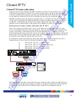
In the scenario shown below, the NVR is set at defaults and the Layer 3 Enhanced CCTV Switch has an
ICR encoder with three analogue camera inputs connected at positions 1, 3 and 4. Position 2 is not used.
The Closed IPTV NVR would be auto configured on consecutive ports, camera 2 would not be allocated
to port 2 which would be registered as assigned to a failed camera.
KBD
USB
NET
AUDIO
IN
VID 1
MON
B
VID 2
VID 3
SATA1
OUT
A
VID 13
VID 8
VID 6
VID 4
VID 5
VID 7
VID 9
VID 10
VID 12
VID 11
VID 14
VID 15
VID 16
ALARMS
RELAYS
SERIAL 1
SERIAL 2
SERIAL 3 PTZ
SERIAL 4 PTZ
AUDIO
IN
OUT
EXP
O
I
IR
MON A
HDMI 1
VID 17
VID 18
VID 19
VID 29
VID 24
VID 22
VID 20
VID 21
VID 23
VID 25
VID 26
VID 28
VID 27
VID 30
VID 31
VID 32
NET
Layer3 Enhanced
CCTV Switch
Shows as
Camfail
Shows as
Camfail
NET 1
NET 0
POE IN
POWER
VID IN
SERIAL 1
SERIAL 2
1
3
4
2
Key
Port Free
Analogue Connection
Single IP connected
Single IP assigned
Multiple IP connection
Unknown
IP detected
Analogue channels take precedence. If an analogue camera is present and connected then it will only
become Port Free if the channel is set to Not Connected on the Closed IP NVR configuration pages.
The de-allocated cameras are added to the Camera->Unallocated Cameras page on the NVR, which
shows a tabulated list of all unallocated cameras connected to the switch, showing all the camera details
(DNS, Auto IP Address, MAC, Classification, Channel number and Native resolution). Each camera has a
drop down list showing all ‘Port Free’ channels available for allocation to the video source.
Any errors in setting up the cameras can be rectified by simply disconnecting and reconnecting the
camera to the switch in whilst configuration mode, which will allow the camera to reallocate. If multiple
changes are made, it is recommended that the NVR is reset after correcting the configuration to ensure
perfect allocation.
IMPORTANT:
For further information refer to the Layer 3 Enhanced CCTV Switch manual
Intelligent Security & Fire Ltd
Summary of Contents for DV-IP NV4
Page 1: ...Installation Guide I n t e l l i g e n t S e c u r i t y F i r e L t d ...
Page 239: ...239 Installation Guide I n t e l l i g e n t S e c u r i t y F i r e L t d ...
Page 240: ...240 NV4 I n t e l l i g e n t S e c u r i t y F i r e L t d ...
Page 244: ...www dedicatedmicros com MI I NV4 E1 0 I n t e l l i g e n t S e c u r i t y F i r e L t d ...

