72
NV4
Startup Camera
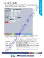
When accessing the Viewer function, select the camera image which
will initially be displayed. If one of the multi display formats has been
selected via the ‘Startup Multi Display’ option, the camera channel
selected here will be displayed in first (top left) position. Subsequent
camera channels will be displayed in sequential order.
Video Output mode
Select the display output that best suits the primary viewing monitor.
Typically PAL Default is most suited for a CRT monitor, PAL Reduced
for a TFT monitor.
Select from:
Safe Mode:
Res: 640 x 512
PAL Default:
Res: 704 x 512
PAL Reduced:
Res: 640 x 512
HD Default:
Res: 1280 x 720
HD 4x3:
Res: 1280 x 720
HDMI Alternate 1: Res: 1280 x 688
HDMI Alternate 2: Res: 1216 x 688
HDMI Alternate 3: Res: 1192 x 676
HDMI Alternate 4: Res: 1264 x 716
HDMI Alternate 5: Res: 1220 x 690
HDMI Alternate 6: Res: 1216 x 688
Video Output mode 2
Select the display output that best suits the secondary viewing monitor,
the options available are the same as shown in ‘Video Output mode’
above.
Note: It will be necessary to reboot the unit to implement any change to the Video Output Mode. The
unit can be rebooted via the Reset (Red) option.
Note: If there is no suitable standard configuration to suit the monitor in use, refer to ‘Appendix F
->Monitor Output’ for details on enabling more options.
Decoder Mode
Select from Normal Display or Decoder Mode. Normal Display allows
cameras to be accessed and controlled via the Viewer menu. In
Decoder Mode, connected cameras can be accessed, viewed or
controlled via Dedicated Micros Pick-a-Point system.
Note: For further information regarding Dedicated Micros Pick-a-Point system, please contact
Dedicated Micros customer services in your region.
Mouse Sensitivity
The sensitivity settings of the mouse can be adjusted from the least
sensitive (1) to the most sensitive (10). The setting can be adjusted
via the slidebar or a number entered directly into the accompanying
textbox. The default setting is 4.
Applet Location
The location of the unit’s Viewer menu applet is displayed. The default
location will always be the applet installed on the unit. If accessing
multiple units via a remote connection, all can be assigned the same
Viewer applet. This will lessen the load time required when accessing
different DVRs/Servers.
For example, if a local unit and a remote DVR are to be accessed, it is
possible to set the Applet location for both DVRs as the local unit.
If viewing the unit remotely, Dedicated Micros provide a remote
applet. This remote applet can be selected via the ‘Set Location’ option.
The applet is located on the website (www.dedicatedmicros.com/software_
release/index_firmware.php). Due to possible bandwidth restrictions on the
network the DVR is located, using this remote applet may improve data
transfer speeds.
Set Location
Select the applet location. Choose from ‘Default location’ i.e. the applet
installed on the unit; or the ‘website’ option i.e. the
remote applet.
Intelligent Security & Fire Ltd
Summary of Contents for DV-IP NV4
Page 1: ...Installation Guide I n t e l l i g e n t S e c u r i t y F i r e L t d ...
Page 239: ...239 Installation Guide I n t e l l i g e n t S e c u r i t y F i r e L t d ...
Page 240: ...240 NV4 I n t e l l i g e n t S e c u r i t y F i r e L t d ...
Page 244: ...www dedicatedmicros com MI I NV4 E1 0 I n t e l l i g e n t S e c u r i t y F i r e L t d ...

