background image

5.5 

Positioning the appliance

5.5.1 

Unpacking the appliance

Caution

Remove all packaging materials. Check that the contents are in­

tact. If you notice a defect, do not use the appliance and contact 

the supplier.

Fig.12

M003102-A

1

2

3

4

5

6

7

8

1. Remove the retaining screw from the fan grille.

2. Turn the grille anticlockwise.

3. Remove the fan grille.

4. Unscrew the two screws from the compressor support part.

5. Remove the compressor support part and discard it.

6. Put the grille back in place.

7. Turn the grille clockwise to fit it back into its housing.

8. Put the retaining screws in place.

5  Installation

300026515 - v09 - 25072017

25

Summary of Contents for KALIKO TWH 200 E

Page 1: ...ASYLIFE SUSTAINABLE COMFORT MW 1000386 1 Australia Denmark Croatia Hungary Jordan Lebanon Malta Serbia Sweden Syria en Installation Manual Thermodynamic water heater KALIKO TWH 200 E TWH 300 E TWH 300 EH ...

Page 2: ...he DHW sensor 13 3 2 2 Appliance specifications 13 3 2 3 Heating curve for the DHW tank as a function of the air temperature 15 3 2 4 Heating curve for the maximum domestic hot water set point reached by the heat pump as a function of the air temperature 15 4 Description of the product 16 4 1 General description 16 4 2 Main components 17 4 3 Operating principle 17 5 Installation 19 5 1 Installatio...

Page 3: ... Modifying the installer parameters 47 6 7 1 Accessing the parameters 47 6 7 2 List of parameters 47 6 7 3 Control system sequence 49 6 7 4 Restoring the factory settings 50 7 Decommissioning 51 7 1 Shutting down the installation 51 7 2 Frost protection 51 8 Maintenance 52 8 1 General instructions 52 8 2 Standard inspection and maintenance operations 52 8 2 1 Refrigerant circuit 52 8 2 2 Check the...

Page 4: ...11 2 1 Specific information 68 Contents 4 300026515 v09 25072017 ...

Page 5: ...l 1 1 2 Water connections The appliance is intended to be permanently connec ted to the water mains Maximum minimum water inlet pressure See Technical specifications section The pressure limiter device must be regularly operat ed in order to remove limescale deposits and ensure that it is not blocked Draining shut off the domestic cold water inlet Open a hot water tap in the installation and then ...

Page 6: ... This appliance must not be powered through an exter nal switch such as a timer or be connected to a cir cuit which is regularly switched on and off by the elec tricity provider Install the appliance in accordance with national rules on electrical installation Wiring diagram See Wiring diagram section Installation and Service Manual Connecting the appliance to the mains See Electrical connections ...

Page 7: ...t the risk of being scalded a ther mostatic mixing valve must be installed on the domestic hot water flow pipes 1 2 Recommendations Warning Only a certified professional who has complete suitable training is authorised to work on the ap pliance and on the installation Warning Before any work switch off the power supply to the appliance 1 3 Liabilities 1 3 1 Manufacturer s liability Our products ar...

Page 8: ...ation and standards Carry out initial commissioning and any checks neces sary Explain the installation to the user If maintenance is necessary warn the user of the obli gation to check the appliance and keep it in good working order Give all the instruction manuals to the user 1 4 Safety data sheet refrigerant fluid R 134a 1 4 1 Product identification Name of the refrigerant fluid R 134a 1 4 2 Haz...

Page 9: ...r In the event of contact with the skin Treat frost injuries like burns Rinse with copious amounts of tepid water do not remove clothing risk of adhesion to the skin If skin burns appear call a doctor immediately In the event of contact with the eyes Rinse immediately in water holding the eyelids well apart at least 15 minutes Consult an ophthalmologist immediately 1 4 5 Fire prevention measures A...

Page 10: ...sources of ignition Ventilate the spillage area mechanically risk of as phyxia Cleaning Decontamination Allow residual product to evaporate 1 4 7 Handling Technical measures Ventilation Precautions to be taken No smoking Prevent the build up of electrostatic charges Work in a well ventilated place 1 4 8 Personal protection Respiratory protection If ventilation is insufficient AX type cartridge mas...

Page 11: ...le after decontamination Destroy in authorised installations Warning Disposal must be completed in compliance with prevailing local and national regulations 1 4 10 Regulations Regulation EU No 517 2014 of the European Parlia ment and of the Council of 16 April 2014 on fluorina ted greenhouse gases and repealing Regulation EC No 842 2006 Classified installations No 1185 1 Safety 300026515 v09 25072...

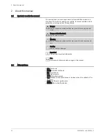
Page 12: ...c shock Risk of electric shock Warning Risk of dangerous situations that may result in minor personal in jury Caution Risk of material damage Important Please note important information See Reference to other manuals or pages in this manual 2 2 Abbreviations HP Heat pump DHW Domestic Hot Water LP Low pressure HP High pressure CFC Chlorofluorocarbon Qpr Standby losses Heat losses in the tank when i...

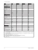
Page 13: ... factory each appliance is tested for the following Water tightness Air tightness Electrical safety 3 2 Technical data 3 2 1 Specifications of the DHW sensor Important Tolerance 5 Ohm Tab 2 Temperature in C 10 20 25 30 40 50 60 70 80 Resistance in ohms 19691 12474 10000 8080 5372 3661 2536 1794 1290 3 2 2 Appliance specifications Tab 3 Model Unit TWH 200 E TWH 300 E TWH 300 EH Heating time 15 51 C...

Page 14: ...ontinuous flow when T 35 K 7 8 litres h 955 6 Flow rate over 10 minutes when T 30 K 7 l 10 min 420 1 Quantity of refrigerant calculated in tonnes of CO2 equivalent 2 Value obtained with an air temperature of 7 C and a water inlet temperature of 10 C according to EN16147 based on LCIE Specifica tions No 103 15 B 2011 3 Value obtained with an air temperature of 15 C and a water inlet temperature of ...

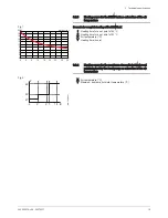
Page 15: ...ir temperature C Y Heating time hours 3 2 4 Heating curve for the maximum domestic hot water set point reached by the heat pump as a function of the air temperature X Air temperature C Y Maximum domestic hot water temperature C Fig 1 0 2 4 6 8 10 12 14 16 18 20 5 0 5 10 15 20 25 30 35 Y X 1 2 MW 1000395 1 Fig 2 MW 1000396 1 51 5 0 5 7 10 X 55 65 Y 3 Technical specifications 300026515 v09 25072017 ...

Page 16: ...e volume of water heated and timer pro gramming Heat exchanger for connection to a boiler or a solar circuit TWH 300 EH 2 4 kW steatite immersion heater Enamelled tank protected by impressed current anode Very thick insulation 0 CFCs The thermodynamic water heater is a hot water tank that can be heated by The heat pump up to 65 C The immersion heater Electrical back up AUTO and Boost mode up to 70...

Page 17: ...prepare domestic hot water The refrigerant circuit is a closed circuit in which the R 134a refrigerant plays the role of an energy carrier The heat from the intake air is transferred to the refrigerant in the finned heat exchanger at a low evaporation temperature The refrigerant is drawn in in vapour form by a compressor which raises it to a higher pressure and temperature and sends it to the cond...

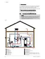
Page 18: ...Temperature controller heat pump 9 Limiting thermostat 10 Temperature controller immersion heater 11 Sensor tube 12 Filter drier 13 Thermostatic expansion valve 14 Ambient air thermostat 15 Evaporator 16 Fan 17 Expansion valve bulb 18 HP pressure switch 19 Solenoid valve for defrosting Fig 4 18 MW 1000360 1 4 Description of the product 18 300026515 v09 25072017 ...

Page 19: ...ow diameter 160 mm EH77 Adapter sleeve diameter 160 mm EH205 Insulated flexible ducting diameter 160 mm length 3 m EH206 Set of two attachment clamps diameter 160 mm EH207 Wall duct diameter 160 mm finishing plate EH208 Aluminium outdoor grille diameter 160 mm EH209 PPE pipe diameter 160 mm length 2x 1 m two sleeves EH272 Two 90 elbows PPE diameter 160 mm two sleeves EH273 Two PPE sleeves diameter...

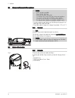
Page 20: ...le ambient transport and storage temperatures 20 to 60 C 5 3 1 Transport Note We recommend shipping the appliance vertically It is possible to transport the appliance horizontally over short distances and only whilst resting on its rear panel Caution It is prohibited to stack or set down the appliance any of its other sides as this may lead to malfunctions or faults 5 4 Choice of the location 5 4 ...

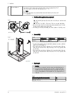
Page 21: ...e appliance on a base frame The base frame must be able to support the load sufficiently at all times Recommended positions Fig 7 1 2 5 3 4 MW 1000366 1 1 Garage Unheated room Enables recovery of the free energy released by your vehicle s engine when switched off af ter use or by household appliances in operation 2 Via outside air Connection to the outside air may lead to overconsumption of electr...

Page 22: ...itate maintenance allow sufficient space around the appliance 200 model Allow a minimum distance of 0 4 m on both sides of the ap pliance and a minimum room height of around 1 84 m for operation with out air ducts 300 model Allow a minimum distance of 0 4 m on both sides of the ap pliance and a minimum room height of around 2 15 m for operation with out air ducts Pipe length Caution Do not use acc...

Page 23: ...Black roof outlet diameter 160 mm EH275 2 0 Waterproof base for 25 to 45 pitched roofs diameter 160 mm EH277 2 0 Reduced elbow kit EH434 6 0 Outdoor grille for air inlet and outlet diameter 160 mm EH558 1 0 Note Add together all of the lengths of accessories used once or more in the installation The total length must not exceed 26 m for a di ameter of 160 mm 5 4 3 Main dimensions TWH 200 E TWH 300...

Page 24: ...690 810 300 455 658 1375 2000 1025 4 1 1 2 3 4 5 6 7 1 Impressed current anode 2 2 4 kW steatite immersion heater 3 Secondary domestic hot water flow G 3 4 4 Solar exchanger or boiler inlet G 3 4 5 Sensor tube for solar or boiler sensor 6 Solar exchanger or boiler outlet G 3 4 7 Domestic cold water inlet G 3 4 1 Adjustable feet 5 Installation 24 300026515 v09 25072017 ...

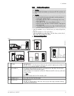
Page 25: ... 12 M003102 A 1 2 3 4 5 6 7 8 1 Remove the retaining screw from the fan grille 2 Turn the grille anticlockwise 3 Remove the fan grille 4 Unscrew the two screws from the compressor support part 5 Remove the compressor support part and discard it 6 Put the grille back in place 7 Turn the grille clockwise to fit it back into its housing 8 Put the retaining screws in place 5 Installation 300026515 v09...

Page 26: ...etc If flushing has to be done using an aggressive product neutralise the rinsing wa ter before disposing of it in the waste water network Note Using hoses which are too short or too rigid encourages the trans mission of vibrations and the production of noises TWH 300 EH Make all the hydraulic connections for the DHW tank using flexible pipes 5 6 1 Connecting the tank to the domestic water circuit...

Page 27: ... least equal to the cross section of the opening of the safety unit outlet to prevent the flow of wa ter being hindered if the pressure is too high The cross section of the discharge pipe from the safety unit must be at least equal to the cross section of the opening on the safety unit outlet Isolation valves Hydraulically isolate the primary and domestic circuits with stop valves to facilitate ma...

Page 28: ...ting to a boiler TWH 300 EH model Caution Before attaching the water connections for the heating circuit and domestic hot water tank heat exchanger the circuits must be flushed to remove any particles which might damage the compo nents safety valve pumps valves etc Fig 14 C003613 C A A Boiler 1 Heating flow 2 Heating return 3 Safety valve 4 Pressure gauge 7 Automatic air vent 9 Isolation valve 11 ...

Page 29: ...tic hot water outlet 61 Thermometer 79 Domestic hot water tank solar exchanger primary outlet 80 Domestic hot water tank solar exchanger primary in let 84 Stop valve with releasable non return valve 85 Primary solar circuit pump 87 Safety valve calibrated to 6 bar 88 Solar expansion vessel 89 Heat transporting fluid container 90 Anti thermosiphon loop 10 x pipe diameter 109 Domestic hot water ther...

Page 30: ...as standard It is possible to install the control system in the living room for greater comfort The user can remotely control programming of domestic hot water pro duction The user is informed directly if the installation malfunctions in any way 5 8 1 Choose a location Install the control system against an internal wall around 1 5 metres from the floor in the carefully chosen pilot room Locations ...

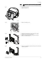
Page 31: ... module from its base 5 Disconnect the control module two wires 6 Unscrew in order to remove the two fixing wires on the base 7 Remove the wire and discard it 8 Unscrew the two fastening screws from the base of the control panel and remove the base Fig 17 C003254 C 1 1 2 Fig 18 MW 1001033 1 3 Fig 19 7 5 4 6 MW C003329 2 Fig 20 8 MW C003408 2 5 Installation 300026515 v09 25072017 31 ...

Page 32: ...rol module at the ap pliance end not supplied 10 Replace the protection cover 11 Replace the front cover 12 Tighten the two screws Fig 21 9 MW C003330 2 Fig 22 MW 1001034 1 10 Fig 23 MW C003334 2 12 13 11 12 5 Installation 32 300026515 v09 25072017 ...

Page 33: ...omply with the prevailing installation standards Power the appliance via a circuit that includes a type D curve omnipolar 16 A circuit breaker with a contact opening distance of 3 mm or more The water heater is delivered with a 3G cable If the power supply cable is damaged it must be replaced by the manufacturer its after sales service or persons with similar qualifications in order to prevent any...

Page 34: ... instruction manual For more information see Installing the control system in the living room page 30 Choose a location page 30 Operations to be carried out on the thermodynamic DHW tank page 31 Positioning the control system in the living room page 33 5 9 3 Accessing the HP HC connection terminal block 1 Unscrew the two screws 2 Remove the front cover Fig 27 MW 1000368 1 1 1 1 2 5 Installation 34...

Page 35: ...lay via a shunt dry contact with the heat pump Fig 29 C003617 F A A B C1 C2 538 kW h 1 1 A1 A2 0 Auto 0 15 45 A 500 mA TEST 16 A 40 A 2 A 30 mA L N X11 2 HP H X11 1 LINE C 1 2 3 4 4 1 Counter 2 Connection circuit breaker 3 AC type differential switch 4 Circuit breaker A 1 5 mm2 voltage cable B 1 5 mm2 Shunt Fig 28 C003335 A HP HC 230V C003335 B 5 Installation 300026515 v09 25072017 35 ...

Page 36: ...ge Fig 30 C1 C2 538 kW h 1 0 15 45 A 500 mA TEST 16 A 40 C003616 E A 2 A 30 mA L N X11 2 HP H X11 1 LINE C L N X11 2 HP HC X11 1 LINE A 1 2 3 4 4 1 Counter 2 Connection circuit breaker 3 AC type differential switch 4 Circuit breaker A 1 5 mm2 voltage cable Set the parameter to 2 The heat pump and back ups are not permitted to operate in peak hours Boost one touch quick heating The two signal wires...

Page 37: ...A 500 mA TEST 16 A 40 C003615 E A 2 A 30 mA L N 1 2 3 4 4 1 Counter 2 Connection circuit breaker 3 AC type differential switch 4 Circuit breaker Easy to install Opt for timer programming to benefit from the peak off peak rate tariff 5 Installation 300026515 v09 25072017 37 ...

Page 38: ...5 mm2 voltage cable 1 The heat pump and the electrical back up are authorised to operate according to the timer programming 2 When the photovoltaic signal is active the tank set point is 62 C and can be adjusted via the parameter 3 If the photovoltaic signal is active when the contact is open set the parameter to 3 4 If the photovoltaic signal is active when the contact is closed set the parameter...

Page 39: ...P 230 V MW SPC003402 2 1 Control panel 2 Fan 3 Solenoid valve for defrosting 4 Compressor 5 Condenser 6 Immersion heater Earth 230 V 230 V power supply L Live N Neutral P Pressure switch R1 R6 Relay S4 Evaporator sensor S5 Room temperature sensor SPL 1 Splice TA Impressed current anode ST Safety thermostat X1 Connecting the impressed current anode X3 S2 Middle domestic hot water temperature sensor...

Page 40: ... Allows automation of domestic hot water production de pending on the setting of the peak off peak rate in put 5 11 Filling the thermodynamic water heater 1 Turn on a hot water tap 2 Open the cold water tap located on the safety unit Ensure that the drain valve on the unit is properly closed 3 When the water flows out from the hot water tap the appliance is full Close the hot water tap Fig 34 MW 1...

Page 41: ...of the week 1 Monday 2 Tuesday 7 Sunday Numeric display Optimisation function active Number of baths available 40 C ltrs Quantity of water litres Decreases the setting values Increases the setting values Confirm key reset Resets the control system after a fault Automatic mode or Comfort mode Eco mode Boost mode days Holiday mode Boost function active using the peak off peak rate input Boost functi...

Page 42: ...he display indicates the number of baths available and the filling level for the tank available quantity of hot water The number of baths is calculated based on a domestic hot water tem perature of 40 C The tank is filled based on the set point temperature Set the and parameters according to the appliance model For more information see Modifying the installer parameters page 47 Accessing the param...

Page 43: ...l Caution After positioning the appliance wait one hour before starting it up Carry out the commissioning operations in the following order 1 Connect to the mains 2 Check that no error codes or messages are shown on the display The domestic hot water temperature set point is factory set to 55 C in comfort mode 3 Select the BOOST operating mode If domestic hot water production is required the compr...

Page 44: ...ve The production of domestic hot water is ensured by the heat pump only After the compressor stops the display showing the available quantity of domes tic hot water may not be full Boost Forced operation active The production of domestic hot water is ensured by the heat pump and the back up simultaneously for a defined period factory setting 6 hours days Holiday Holiday period Production of domes...

Page 45: ...uence Back up set point C Compressor set point C 6 6 2 Counters Displaying the counters 1 Press the MENU key once The menu is displayed 2 Press the key three times The menu is displayed 3 Press the MODE key to go into the Counters menu The number for the counter is shown on the right hand side of the screen 4 Use the and keys to switch between counters see table be low 5 To exit this menu press th...

Page 46: ...owered on h 6 Instantaneous output W Resetting the counters to zero 1 Press the MENU key once The menu is displayed 2 Press the key three times The menu is displayed 3 Press the MODE key to go into the Counters menu The number for the counter is shown on the right hand side of the screen 4 Use the and keys to switch between counters 5 Press the reset key to reset the meter displayed to zero 6 Conf...

Page 47: ...s the menu The parameter appears 5 Scroll through the parameters using the or keys 6 To edit a parameter press the MODE key The parameter value flashes 7 Adjust the required value using the or keys 8 Confirm the value with the MODE key 6 7 2 List of parameters Tab 12 List of parameters Parameter Description Adjustment range Factory setting Domestic hot water set point in Auto mode 25 to 70 C 55 C ...

Page 48: ...y tariff information input is used to activate the Boost function with compressor and back up HP1 Boost activated contact open HC0 Boost deactivated contact closed 0 6 0 Automatic switch to summer time last Sunday in March and to winter time last Sunday in October 0 Function not active for countries where the time changes on other dates or daylight saving time is not used 1 Function active 0 1 1 D...

Page 49: ... a demand for the hydraulic back up 0 1 0 Domestic hot water set point used for anti legionella function 55 to 70 C 65 C Output of the immersion heater Unit 0 1 kW 16 255 24 Water temperature difference between the tank temperature and the set point before the restart of the compressor 1 to 15 C 3 C 1 Minimum room temperature for compressor operation 5 to 20 C 5 C 1 Maximum room temperature for co...

Page 50: ...ress the and keys for 5 seconds The rSt menu is displayed 2 Press the MODE key to restore the factory settings for all the pa rameters Fig 48 C003495 C 3 1 4 3 4 1 2 MENU MODE Fig 49 C004193 A 1 4 3 4 1 2 MENU MODE 6 Commissioning 50 300026515 v09 25072017 ...

Page 51: ...re protec tion against corrosion The appliance s frost protection remains active 7 2 Frost protection During extended periods of absence holidays program the correspond ing number of days The temperature of the water contained in the tank is maintained at 10 C See User Guide 7 Decommissioning 300026515 v09 25072017 51 ...

Page 52: ... are important for the following reasons To guarantee optimum performance To extend the life span of the equipment To provide an installation which offers the customer optimum comfort over time Caution The control components must never come into contact with water Before starting any cleaning disconnect the mains power supply plug or power off the appliance 8 2 Standard inspection and maintenance ...

Page 53: ...stic cold water inlet 2 Drain the water heater 3 Turn on a hot water tap 4 Open the valve on the safety unit 5 Remove the insulation from the inspection hatch 6 Take out the domestic hot water sensor 7 Remove the inspection hatch 13 mm spanner 8 Until December 2015 Remove the two bulbs from the safety ther mostat From January 2016 Take out the safety thermostat bulb 9 Remove the limescale deposite...

Page 54: ...ances the water heater s insula tion Remove limescale deposits from the bottom of the tank Remove limescale deposits from the exchanger to guarantee its per formance 7 Remount the unit Caution Each time it is opened the lip gasket retainer ring unit must be replaced to guarantee a tight seal Place the positioning lug on the gasket towards the outside of the water heater 8 After reassembly check th...

Page 55: ...No Date Checks made Remarks By Signature 8 Maintenance 300026515 v09 25072017 55 ...

Page 56: ...essure switch alarm Note Domestic hot water production is en sured by the back up if the back up is authorised Check the compressor power supply Check the pressure switch connection Maximum domestic hot water temperature excee ded when domestic hot water production is not guaranteed by either the compressor or the back up Check the top domestic hot water sensor con nection Check that the back up i...

Page 57: ...e started by pressing the RESET key Protection against corrosion is not guaranteed The impressed current anode has short circuited Check that the connection cable between the PCU PCB and the anode has not short circuited Check that the anode has not short circuited Note Production of domestic hot water is stopped for 72 hours but may be re started by pressing the RESET key Protection against corro...

Page 58: ...ction is not guaranteed Bad connection Check whether the sensor is connected Check the link and the connectors Check that the sensor has been correctly fitted Sensor failure Check the Ohmic value of the sensor Replace the sensor if necessary The room temperature sensor is has short circuit ed Note Domestic hot water production is en sured by the back up if the back up is authorised Bad connection ...

Page 59: ...ck the position of the temperature sensor in the evaporator Check that the fan is working correctly Check that the condensates can flow freely The LP pressure switch alarm has been active for more than 120 seconds Note Domestic hot water production is en sured by the back up if the back up is authorised Check the position of the temperature sensor in the evaporator Check that the fan is working co...

Page 60: ...the error Use the and keys to scroll through the list of errors Use the MENU key to return to the list of errors 9 2 2 Displaying lockouts bL 1 When the bL menu is displayed press the MODE key 2 The code for the most recent lockout is displayed along with its time and date displayed in turn 3 Press the MODE key to access the details of the lockout Use the and keys to scroll through the list of loc...

Page 61: ... the list 10 2 Spare parts lists until December 2015 Fig 57 Heat pump MW 1000417 1 8 29 21 16 24 22 19 13 1 18 5 15 28 14 6 2 3 12 17 11 4 7 10 4 20 23 25 26 27 Markers References Descriptions 1 SFH41000 Base frame 2 7606446 Air sensor 3 SFH22039 Evaporator sensor 4 SFH32178 Main electrical harness 5 SFH24053 Coil 6 SFH40173 Sensor bracket 7 SFH31034 Control module 8 SFH20050 Compressor 10 SFH3317...

Page 62: ...racket for control panel 19 SFH41002 Air duct 20 SFH98172 Foam gasket 21 SFH40171 Compressor bracket 22 SFH25298 Heat exchanger 23 SFH12102 Valve plug 24 SFH22056 0 5 m tank sensor Connector 25 SFH22057 1 5 m tank sensor Connector 26 SFH22058 2 m tank sensor Connector 27 200020513 Heat pump screw bag 28 7611992 Cabled high pressure pressure switch 29 7610320 Compressor insulation 10 Spare parts 62...

Page 63: ...ferences Descriptions 1 7614973 Heating element 2 97862390 Housing for heating element 3 7607345 Retaining plate 4 95363327 Thermostat 5 200011080 Connection cable black x3 6 300019070 Connecting bridge 7 89534902 Earth wire 8 300025717 Power supply cable for the heating element 9 95013133 Lip gasket diameter 82 mm 10 Spare parts 300026515 v09 25072017 63 ...

Page 64: ...Retainer ring 5 mm 20 300025193 Nozzle 21 300025194 Grille 22 300025192 Top cover 23 200020278 Back cover Spacers Screws 24 200020279 Front cover Spacers Screws 25 300025216 Trim panel 26 300025930 Front cover height 1140 mm 26 300025931 Front cover height 1495 mm 28 94994712 PVC pipe diameter 16x12 29 S101017 Pipe clamp 135 30 97860646 Adjustable foot M10x35 x3 31 300025648 3 4 dielectric union 3...

Page 65: ...sure pressure switch 4 SFH32178 Main electrical harness 5 SFH24053 Coil 6 SFH40173 Sensor bracket 7 SFH31034 Control module 8 SFH20050 Compressor 10 SFH33170 Earthing connector 11 SFH37008 Motorised fan 12 7641131 Control system PCB 13 SFH23108 Expansion valve 14 SFH24052 Solenoid valve 15 SFH22234 Low pressure pressure switch 16 SFH21038 Filter drier 17 SFH40172 Fan bracket 18 SFH41001 Bracket fo...

Page 66: ...642838 Tank sensor 25 200020513 Heat pump screw bag 26 7622250 Compressor insulation 27 7680708 Gasket 28 7661361 Control panel insulation 29 7660902 Evaporator insulation Fig 60 Thermodynamic water heater 9 1 4 3 2 5 6 16 34 33 14 13 7 17 20 28 29 21 30 31 18 8 20 15 23 22 26 24 31 32 19 10 12 11 MW 1000420 2 37 25 35 36 10 Spare parts 66 300026515 v09 25072017 ...

Page 67: ...1795 Holding plate 17 95365613 Sensor tube separator 18 89525501 Complete top inspection hatch 19 89705511 Gasket 7 mm Retainer ring 5 mm 20 300025193 Nozzle 21 300025194 Grille 22 300025192 Top cover 23 200020278 Back cover Spacers Screws 24 200020279 Front cover Spacers Screws 25 300025216 Trim panel 26 300025930 Front cover height 1140 mm 26 300025931 Front cover height 1495 mm 28 94994712 PVC ...

Page 68: ...eters for heat pump water heaters TWH 200 E TWH 300 E TWH 300 EH Daily electricity consumption Qelec kWh 3 205 4 881 6 066 Declared load profile L XL XL Sound power level indoors 1 LWA dB A 57 57 57 Storage volume V l 215 0 270 0 265 0 Mixed water at 40 C V40 l 274 380 383 1 If applicable Circulating pump Note The benchmark for the most efficient circulating pumps is EEI 0 20 Disposal and Recyclin...

Page 69: ...11 Appendix 300026515 v09 25072017 69 ...

Page 70: ...11 Appendix 70 300026515 v09 25072017 ...

Page 71: ...hnological information contained in these technical instructions as well as any drawings and technical de scriptions supplied remain our property and shall not be multiplied without our prior consent in writing Subject to alterations ...

Page 72: ...DE DIETRICH THERMIQUE 57 rue de la Gare F 67580 MERTZWILLER BP 30 MW 8000001 11 300026515 v09 25072017 300026515 001 09 ...

Reviews: