5.9
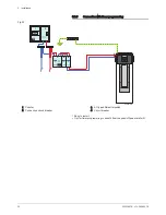
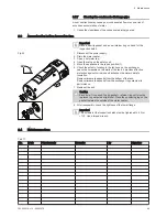
Electrical diagram
Fig.24
3
3
4
P
C
U
-1
9
5
2
θ
°
C
1
2
1
2
X
8
1
5
4
4
1
2
6
1
2
3
1
2
2
1
2
3
X
-H
C
1
2
1
X
7
2
θ
°
C
2
2
1
1
1
2
X
3
1
X
1
1
2
θ
°
C
2
1
2
X
4
1
3
X
5
5
6
2
θ
°
C
1
2
1
1
2
4
P
C
O
M
N
C
N
O
L
S
P
L
1
N
1
2
3
4
1
X
-B
1
1
2
R5
R4
R3
R1
R2
S1
S2
TA
S4
S5
P
TS
X
6
1
2
2
4
R6
2
5
1
2
3
K
L
IX
O
N
H
P
230 V
MW-SPC003402-2
1 Control panel
2 Fan
3 Solenoid valve for defrosting
4 Compressor
5 Condenser
6 Immersion heater
Earth
230 V 230 V power supply
L Live
N Neutral
P Pressure switch
R1–R6 Relay
S4 Evaporator sensor
S5 Room temperature sensor
SPL1 Splice
TA Impressed current anode
ST Safety thermostat
X1 Connecting the impressed current anode
X3–S2 Middle domestic hot water temperature sensor
X4–S1 Top domestic hot water temperature sensor
X5 Room temperature sensor, evaporator, pressure
switch
X6 Control panel connection
X7 Hydraulic back-up control terminal board
5 Installation
34
300026515 - v10 - 28082018


