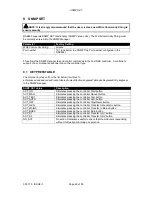
background image

Connecting to the Gateway Management Pages 


Page 31 of 50 

057-179   ISSUE: 3 


7.2.6.2 

FIRMWARE UPGRADE BY USB MEMORY STICK 

 
When available, firmware upgrade files are available from Deep Sea Electronics PLC website 
www.deepseaplc.com. 
 
To do this you will need : 


Firmware update filed from DSE. This file must be called 0892-01.bin 


USB flash memory stick formatted to 

FAT

 
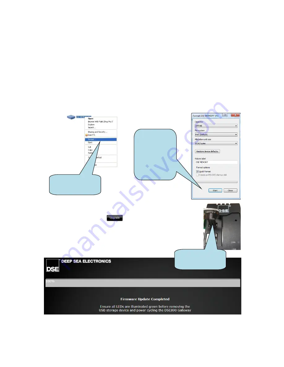
To Format a USB stick to the FAT File System : 


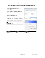
Insert memory stick into PC USB port. 


Browse to 

Computer

 in Windows Explorer. Identifty the memory stick, Right Click the 

device and select 

Format.


Select FAT and click 

Start


Copy the firmware upgrade file onto the USB flash memory stick and 
insert 

this into the ‘USB Host’ socket of the DSE892 Gateway. 


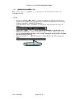
Once inserted, click the 

 button. The module is restarted and 

the upgrade process begins. The PC screen shows the progress of the 
upgrade.  


Once complete, Check that all the LEDs are illuminated on the DSE892. 
This shows that the updgrade is successful.  


Next, remove the USB memory device and remove the DC power from 
the DSE892. Wait a few seconds, then reapply DSE power.  


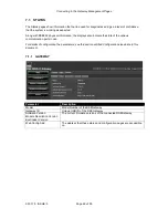
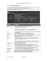
USB flash memory 
stick inserted into the 
DSE892 Gateway 


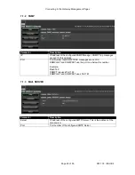
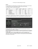
Right Click 

context 

menu

 of USB flasm 

memory device 


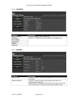
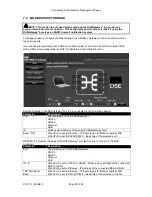
Format tool for 
USB flash 
memory.  
Ensure you have 
selected the 
correct disk 
before clicking 

Start!


Summary of Contents for DSE892 SNMP

Page 1: ...057 179 ISSUE 3 DEEP SEA ELECTRONICS PLC DSE892 SNMP Gateway Manual Document Number 057 179 Author Anthony Manton ...

Page 2: ...plications for the copyright holder s written permission to reproduce any part of this publication should be addressed to Deep Sea Electronics Plc at the address above Any reference to trademarked product names used within this publication is owned by their respective companies Deep Sea Electronics Plc reserves the right to change the contents of this document without prior notice Amendments since...

Page 3: ...PICAL CONNECTION TO DSE CONTROLLERS 14 4 4 1 ADDING THE CONTROLLER TO THE DSE892 14 4 4 2 DEVICE COMPATIBILITY 15 4 4 3 USB SINGLE CONTROLLER 16 4 4 4 RS232 SINGLE CONTROLLER 16 4 4 5 RS485 SINGLE CONTROLLER 17 4 4 6 RS485 MULTIPLE CONTROLLER 17 4 4 7 ETHERNET SINGLE CONTROLLER 18 4 4 8 ETHERNET MULTIPLE CONTROLLER 18 4 5 TYPICAL CONNECTION TO SNMP MANAGEMENT SYSTEM 18 5 CONTROLS AND INDICATIONS 1...

Page 4: ...34 7 3 1 1 MODULE EVENTS 34 7 3 1 2 INSTRUMENTATION EVENTS 36 7 4 MODBUS PASSTHROUGH 38 7 4 1 EXAMPLE OF MODBUS GATEWAY SETTINGS 39 7 5 MODULE INSTRUMENTATION 40 7 5 1 DETAILED INSTRUMENTATION 40 8 SNMP GET 41 8 1 CONTROLTABLE 41 8 2 INSTRUMENTTABLE 42 9 SNMP SET 46 9 1 KEYPRESSTABLE 46 10 FAULT DIAGNOSIS 47 11 MAINTENANCE SPARES REPAIR AND SERVICING 49 11 1 WARRANTY 49 11 2 DISPOSAL 49 11 2 1 WEE...

Page 5: ...MP Gateway communicates to the connected controller s monitoring the instrumentation and operating state If this data changes SNMP TRAP information is generated and sent to the SNMP Manager Additionally emails can be configured to be set to one or two email addresses DSE892 SNMP Gateway also supports GET functionality to read information from the host controller and SET functionality to allow the ...

Page 6: ...he DSE892 Gateway reports information via SNMP TRAP messages to the manager Additionally the DSE892 responds to GET SET messages from the SNMP manager to allow the host controller s operating mode to be changed or instrumentation values to be retrieved Many third party SNMP managers exist DSE do not produce or supply SNMP managers 2 1 PRINCIPLE OF SNMP COMMUNICATION 2 2 MIB FILE SNMP does not spec...

Page 7: ...h at initial power up Typical Operating current 630 mA at 12 V DC 315 mA at 24 V DC 3 2 CONFIGURABLE I O Number 4 configurable general purpose input outputs Not currently fitted to the DSE892 RESERVED for future use Rating TBA 3 3 TERMINAL SPECIFICATION Connection type Screw terminal rising clamp no internal spring Min cable size 0 5 mm AWG 20 Max cable size 2 5 mm AWG 14 3 4 USB HOST CONNECTOR Th...

Page 8: ...o NOTES 1 Received Line Signal Detector Data Carrier Detect 2 Received Data 3 Transmit Data 4 Data Terminal Ready 5 Signal Ground 6 Data Set Ready 7 Request To Send 8 Clear To Send 9 Ring Indicator View looking into the male connector on the module 3 5 1 NULL MODEM CABLE WIRING DSE Controller with RS232 Null Modem Cable DSE892 Gateway ...

Page 9: ...lers in a daisy chain RS485 network Ensure termination resistors 120 are fitted as shown to the ends of the link as per RS485 standard PIN No NOTES A Two core screened twisted pair cable 120 impedance suitable for RS485 use Recommended cable type Belden 9841 Max distance 1200 m 1 2 km when using Belden 9841 or direct equivalent B SCR DSE892 ...

Page 10: ...pe 2 green solid green solid 3 white orange stripe white orange stripe 4 blue solid blue solid 5 white blue stripe white blue stripe 6 orange solid orange solid 7 white brown stripe white brown stripe 8 brown solid brown solid NOTE DSE Stock a 2m 2yds Ethernet Cable Part number 016 137 Alternatively they can be purchased from any good PC or IT store As the Gateway is autosensing either a straight ...

Page 11: ...oles M4 clearance Mounting hole centres 73 mm x 137 mm 2 89 x 5 39 Dimensions in mm 3 9 APPLICABLE STANDARDS Minimum Temperature 30 C 22 F Maximum Temperature 70 C 158 F Degrees of Protection Provided by Enclosures IP21 NEMA Rating Enclosure type 1 indoor use only SNMP DSE892 Gateway supports SNMP V2c In line with our policy of continual development Deep Sea Electronics reserve the right to change...

Page 12: ...d mounting details see the section entitled Specification Dimensions elsewhere in this document 4 1 USER CONNECTIONS 4 1 1 CONNECTOR A DC SUPPLY AND CONFIGURABLE OUTPUTS Terminal Function Recommended size 1 DC supply negative 1 0 mm AWG 18 2 DC supply positive 1 0 mm AWG 18 3 RESERVED 4 RESERVED 5 RESERVED 6 RESERVED 4 1 2 CONNECTOR B RS485 Terminal Function Recommended size A RS485 A 0 5 mm AWG 2...

Page 13: ... Page 13 of 50 057 179 ISSUE 3 4 2 TYPICAL WIRING DIAGRAM 4 3 SYSTEM OVERVIEW MODEL 0892 DSE CONTROLLER S SNMP MANAGER Connection to DSE Controller s USB RS232 RS485 Ethernet Connection to SNMP manager via ethernet ...

Page 14: ... in communications failure indicated by a RED communications port LED The DSE892 is factory set to accept connection via the USB port If this is not the port to be used you must configure the DSE892 for the required port as detailed elsewhere in this document Remove the DC supply from the DSE892 AND the connected controller s Connect the new controller to the chosen communications port Apply the D...

Page 15: ...port for legacy devices is withdrawn from the DSE892 at regular udpates To check on the possibility of support for legacy devices no longer listed below please contact support deepseaplc com NOTE Not all variants are available in all markets NOTE Not all instrumentation is available with all controllers Refer to the Configuration Suite PC Software manual relevant to your controller for details of ...

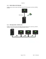
Page 16: ...ion utilises a standard USB A USB B cable NOTE DSE Stock a 2m 2yds USB Cable DSE Part No 016 125 Alternatively they can be purchased from any good PC or IT store 4 4 4 RS232 SINGLE CONTROLLER RS232 connection utilises a standard RS232 Null modem crossover cable USB cable RS232 cable ...

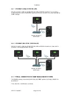
Page 17: ...utilises twisted pair RS485 cable with 120 termination resistors as per RS485 standard 4 4 6 RS485 MULTIPLE CONTROLLER RS485 connection utilises twisted pair RS485 cable with 120 termination resistors as per RS485 standard to connect to a maximum of five supported DSE controllers RS485 cable ...

Page 18: ...with the SNMP manager 4 4 8 ETHERNET MULTIPLE CONTROLLER Ethernet connection utilises a standard Ethernet cable with RJ45 connectors to connect with a maximum of five supported DSE controllers 4 5 TYPICAL CONNECTION TO SNMP MANAGEMENT SYSTEM The DSE892 gateway communicates with third party SNMP systems confirming to SNMP V2c specification This connection is via Ethernet or internet Internet or Eth...

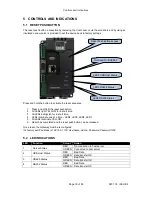
Page 19: ... LEDs illuminate one at a time LED4 LED3 LED2 LED1 5 All LEDs illuminate YELLOW 6 Reset has completed and the reset push button can be released Once reset the Gateway must be reconfigured It s factory set IP address is 192 168 1 100 Username Admin Password Password1234 5 2 LED INDICATIONS LED Function Colour Action 1 Server Status RED No connection to host server GREEN Connected to host server 2 U...

Page 20: ... for Google Chrome web browser 6 1 2 INTERNET EXPLORER The management pages are optimised for Internet Explorer 10 and above 6 1 3 MOZILLA FIREFOX The management pages are optimised for Mozilla Firefox 6 1 4 SMARTPHONE BROWSERS While not designed specifically to work with Smartphone webbrowsers The management pages are work with any mobile browser fully compatible with Google Chrome Internet Explo...

Page 21: ... DSE892 ethernet port directly to your PC Ethernet port You can use either a straight through or crossover network cable Set the PC IP address as shown Using Google Chrome Microsoft Internet Explorer or Mozilla Firefox enter the IP address of the gateway Enter the username and password of the Gateway NOTE Username and Password are both CASE SENSITIVE Factory Settings IP Address Username Password 1...

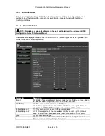
Page 22: ...e the state of the various communication ports in use For details of configuration the parameters see the section entitled Configuration elsewhere in this document 7 1 1 GATEWAY Parameter Description Model Model Number of the DSEGateway Gateway ID Unique USB ID of the DSEGateway Software Version Module Description Version Bootloader Version The current firmware versions of the connected DSEGateway...

Page 23: ...t to this address Port Port Number that SNMP TRAP messages are sent to SNMP GET and SNMP SET use the port one below this number Example Port 162 SNMP Trap uses Port 162 SNMP GET and SNMP SET uses Port 161 7 1 3 MAIL SERVER Parameter Description Server IP address of the configured SMTP Server This is the address of the email server Port Port number of the configured SMTP Server ...

Page 24: ...e DSEGateway MAC Address Subnet Mask Gateway IP DNS IP Hostname 7 1 5 MODBUS Parameter Description Packets Sent Shows the number of data request packets sent to the connected Host Controllers Packets Received Shows the number of data request packets received from the connected Host Controllers Received shoud increase everytime that Sent increases to show that the connected Host Controller s is are...

Page 25: ...d to bind a specific IP address to the MAC Address of the DSE892 This allows the SNMP manager to be easily configured with the IP address of the DSE892 Static IP Factory setting 192 168 1 100 Subnet mask Factory setting 255 255 255 0 Gateway IP IP address of the internet router that the DSE892 is connected to DNS IP IP address of the Domain Name Service Usually this is the same as the Gateway IP H...

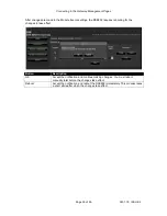
Page 26: ... Network manager of the site that the DSE892 is connected to before making any changes to these settings Parameter Description IP Port The IPV4 network location of the SNMP manager Get password The SNMP Read Community String Factory setting public Set password The SNMP Write Community String Factory setting private ...

Page 27: ...nd Email blank for one recipient Sender The Name and Email address that the email will appear to have been sent from Server Network address of the SMTP server used to send emails Port Which network TCP port is used to send SMTP emails Typically port 587 is used for SMTP Some legacy systems may still be configured to 25 Domain The network Domain Name where the DSE892 is part of a Domain system Requ...

Page 28: ... or pm when 24h Format is not selected Date Time Set the date and time local to the site Get Time Gets the time from the PC and enters this into the Date and Time boxes above Save Sends the values entered to the DSE892 Gateway 7 2 5 LOGIN This page allows the Username and Password of the DSE892 Gateway to be changed to suit user requirements Factory Settings Username Password Admin Password1234 ...

Page 29: ...de firmware from TFTP Server See section entitled Firmware Upgrade by TFTP for full description Upgrade firmware from USB Drive See section entitled Firmware Upgrade by USB Memory Stick for full description Update Module Descriptions From TFTP Server When available this allows the latest version of Module Description files to be downloaded from the DSE server These files instruct the DSE892 about ...

Page 30: ...ct DNS entries in the System Settings IP section of the DSE892 configuration Select the required version number from the drop down list box and press the Upgrade button The DSE892 connects to the TFTP server and begins the update The status LEDs on the DSE892 will alternate to show the download is in progress This may take several minutes When complete all LEDs illuminate yellow for one second aft...

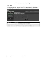
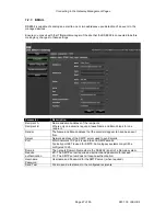
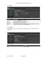
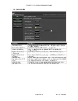
Page 31: ...d select Format Select FAT and click Start Copy the firmware upgrade file onto the USB flash memory stick and insert this into the USB Host socket of the DSE892 Gateway Once inserted click the button The module is restarted and the upgrade process begins The PC screen shows the progress of the upgrade Once complete Check that all the LEDs are illuminated on the DSE892 This shows that the updgrade ...

Page 32: ...d restarted Examples of this are Changes to the DSE892 Username or Security Code Changes to the IP Setup or SNMP Setup Where this is required the message Please Reboot to Apply Changes appears under the navigation menu as shown to the left Press Reboot Now to restart the device The PC screen shows a progress bar as this process is undertaken ...

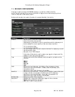
Page 33: ...troller For example you could use the generator name Example Volvo TAD9 Genset2 Once entered this name is used to create a new page to configure what the Gateway is to monitor in this application Type Used to select which of the Gateway s ports are used for connection to this controller RS232 RS485 Ethernet USB ID IP When Port is set to Ethernet IP address of the connected controller When Port is ...

Page 34: ...nd or email notification Parameter Description Event For details of supported Events in your connected controller you are referred to the relevant DSE Configuration Suite PC Software Manual SNMP Trap This event will not generate an SNMP trap Where supported by the connected controller s event log the Gateway generates an SNMP TRAP message upon activation of this event E Mail Recipient 1 E Mail Rec...

Page 35: ...he DSE892 requires rebooting for the changes to take effect Button Description OK Accept the notification and continue making changes You must reboot manually later before the changes take effect Reboot Accept the notification and reboot the DSE892 immediately This process takes a short while after which the changes take effect ...

Page 36: ...ful name For example this could be the name of the instrument in the connected controller ie Oil Pressure Pol Trip Val Ret Val When Pol Is set to When the value rises past the Trip Val setting the configured actions are taken The Value must fall below the Ret Val setting before the condition is considered to be back to normal When the value falls below the Trip Val setting the configured actions a...

Page 37: ...adecimal value Modbus address 0x0504 a value consisting of a single 16 bit unsigned register is monitored This has been given a description of Turbo PR 1 When the value falls below the Trip Val setting of 10 an SNMP trap is generated and an email sent to Recipient1 The Value must rise above the Ret Val setting of 12 before the condition is considered to be back to normal The value SNMP Instance of...

Page 38: ...ort this is connected to the monitoring device Parameter Description Port The incoming port of the DSEGateway RS232 RS485 Ethernet USB ID Modbus slave address of the selected DSEGateway port Baud Port When Port is set to Ethernet TCP port to use for Modbus usually 502 When Port is set to RS232 RS485 Baud rate of the selected port MASTER To module Settings of the DSEGateway port that is used to con...

Page 39: ...g modbus requests from the external monitoring system on Ethernet TCP Port 504 This is being transferred to the DSE controller via the RS232 port on the DSEGateway using slave ID 10 baud rate 115200 NOTE RS485 is a single master system This means that you must only create one entry for RS485 in the Slave column Each entry in the Master column must communicate with controllers with unique Slave Id ...

Page 40: ... instrumentation page shown overleaf The name of each page is taken from the name of the connection in the Modbus Passthrough page 7 5 1 DETAILED INSTRUMENTATION NOTE Only functions supported by the connected controller is shown For a list of instrumentation and control mode buttons you are referred to the relevant controller s Operator Manual available from www deepseaplc com ...

Page 41: ...er enterprises dseVendor dseProduct in the SNMP manager Information List Description dseEventSection Description of the event TRAP dseInstrumentsSection InstrumentTable A predefined list of commonly required instruments dseInstrumentsSection CustomInstrumentTable A list containing the user configured Custom Instruments in the DSE892 configuration controlTable The current selected host controller o...

Page 42: ...Generator Frequency 0 1 Hz genL1L2Volts Generator L1 L2 Volts V AC genL2L3Volts Generator L2 L3 Volts V AC genL3L1Volts Generator L3 L1 Volts V AC genECurrent Generator Earth Current A mainsFreq Mains Frequency 0 1 Hz mainsL1Volts Mains L1 Volts V AC mainsL2Volts Mains L2 Volts V AC mainsL3Volts Mains L3 Volts V AC mainsL1L2Volts Mains L1 L2 Volts V AC mainsL2L3Volts Mains L2 L3 Volts V AC mainsL3...

Page 43: ...3 var var mainsTotalVAr Mains Total var var mainsPowerFactorL1 Mains L1 Power Factor 1 to 1 mainsPowerFactorL2 Mains L2 Power Factor 1 to 1 mainsPowerFactorL3 Mains enerator L3 Power Factor 1 to 1 mainsAvgPowerFactor Mains Average Power Factor 1 to 1 busTotalWatts Bus Total Watts W busL1VA Bus L1 VA VA busL2VA Bus L2 VA VA busL3VA Bus L3 VA VA busTotalVA Bus Total VA VA busL1VAr Bus L1 var var bus...

Page 44: ...urs 0 1 kW h s2Kwh S2 Positive kW Hours 0 1 kW h s2Kva S2 kVA Hours 0 1 kVA h s2Kvar S2 kVAr Hours 0 1 kVAr h s1Kwh S1 Positive kW Hours 0 1 kW h s1Kva S1 kVA Hours 0 1 kVA h s1Kvar S1 kVAr Hours 0 1 kVAr h s1Frequency S1 Frequency 0 1 Hz s1L1Volts S1 L1 N Voltage 0 1 V s1L2Volts S1 L2 N Voltage 0 1 V s1L3Volts S1 L3 N Voltage 0 1 V s1L1L2Volts S1 L1 L2 Voltage 0 1 V s1L2L3Volts S1 L2 L3 Voltage 0...

Page 45: ...Watts S1 Total Watts 0 001 kW s1L1Va S1 L1 VA 0 001 kVA s1L2Va S1 L2 VA 0 001 kVA s1L3Va S1 L3 VA 0 001 kVA s1TotalVa S1 Total VA 0 001 kVA s1L1Var S1 L1 VAr 0 001 kVAr s1L2Var S1 L2 VAr 0 001 kVAr s1L3Var S1 L3 VAr 0 001 kVAr s1TotalVar S1 Total kVAr 0 001 kVAr s1L1PowerFactor S1 Power Factor L1 0 01 pf s1L2PowerFactor S1 Power Factor L2 0 01 pf s1L3PowerFactor S1 Power Factor L3 0 01 pf s1Averag...

Page 46: ...ises dseVendor dseProduct dseInstrumentSection keypressTable dseKeypressEntry keypress in the SNMP manager SNMP SET Value Description ACT_ON Simulates pressing the controller Start button ACT_MAN Simulates pressing the controller Manual button ACT_TEST Simulates pressing the controller Test button ACT_AUTO Simulates pressing the controller Auto button ACT_OFF Simulates pressing the controller Stop...

Page 47: ...he Gateway is 192 168 1 100 Set your PC to 192 168 1 99 then enter http 192 168 1 100 into your browser Communication port LEDs are flashing GREEN This is normal The ports flash green when data is successfully received from the connected controller Port LEDs illuminate RED for a few seconds at power up of the DSE892 During the startup sequence the status LED illuminate RED This is normal and if po...

Page 48: ... number below this if using GET and or SET SNMP Traps are not being received by the SNMP Manager Check that any firewall between the DSE892 and the SNMP Manager is configured to allow through the traffic on the selected SNMP port Check that the DSE892 is set to send TRAP messages to the correct IP address of the SNMP Manager Check that the DSE892 network settings are correct verify with the IT man...

Page 49: ... 1 6 6 way 5 08mm 007 446 A B SCR 3 way 5 08mm 007 174 If you require antennae or USB cables please contact our Sales department using the part numbers below Connection Description Part No USB USB A to USB B DSE892 to host controller 016 125 11 1 WARRANTY DSE provides limited warranty to the equipment purchaser at the point of sale For full details of any applicable warranty you are referred to yo...

Page 50: ...This Page Is Intentionally Blank ...

Reviews: