background image

HD Multi SeaCam

®

Operator’s Manual

16

1.5  

Factory Reset

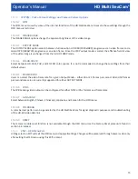
Returning the HD Multi SeaCam camera to the factory supplied settings can be done through the Tristate input control 

pins.

1.5.1 

Tristate Input Factory Reset Method

To reset the camera using the two Tristate inputs, hold Tristate A and Tristate B high for 


5 seconds. After 5 seconds the 

camera will undergo a brief reset sequence during which the camera video outputs will be disabled and there will be 

no image available. After the successful factory reset the output video drivers will be enabled again and the camera will 

be reset to the factory default settings. This process takes approximately 20-30 seconds.

Summary of Contents for HD Multi SeaCam

Page 1: ...7 USA www deepsea com sales deepsea com Original Instruction 1 REV 11 21 16 HD Multi SeaCam Record product serial number below as it appears on the nameplate Serial Connector Type Pin outs HD SDI Coax Ground Pin ____ Power Pin ____ Analog Video Pin ____ Tristate A PIn ____ Tristate B Pin ____ HD Multi SeaCam ...

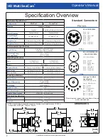
Page 2: ...2MP CMOS 16 9 0 1 Lux Scene Illumination 0 2 Lux 50 IRE 3 0 Lux Color Resolution 1920 H x 1080 V Signal to Noise 50 dB HD Video Output2 HD SDI 1 5 Gb s 1080p 30 Analog Video Output3 CVBS NTSC PAL Selectable Electrical Specifications Power 10 32 VDC 2W max Current 200mA max Standard Connectors Dimensions 1 6 000 m depth rating is limited by connector housing crush depth exceeds 10 000 m 2 Configura...

Page 3: ...2 8 1 26 32 0 1 20 30 5 2 22 56 4 5 46 138 6 inch mm 2 04 51 7 2 72 69 1 5 91 150 2 6 93 176 1 2 29 58 1 1 20 30 5 2 22 56 4 5 08 129 0 6 10 154 9 2 29 58 1 inch mm Dimensions 1 69 42 9 1 00 25 4 1 59 40 3 1 00 25 4 4x 1 4 20 OR 4x M6x1 Fiber Coax Bracket 2 72 69 1 4 88 124 0 6 98 177 3 2 04 51 7 1 26 32 0 4 05 102 8 6 14 156 1 2 22 56 4 1 20 30 5 1 26 32 0 inch mm ...

Page 4: ...fety Symbols 4 General Notes and Warnings 4 Pre and Post Dive Inspection 4 5 Operation Procedure 5 Operation Instruction 5 Camera Output 5 Flooding Repair Procedure 5 Troubleshooting 5 RMA Procedure for Repair 5 6 Warranty Information 6 7 Limited Warranty 7 Appendix A Tristate Input Camera Control 8 16 ...

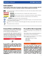
Page 5: ...rientation before use It is very important when preparing the system for deployment that the cable at both the camera and topside ends be carefully dressed to provide complete strain relief to the connectors Failure of the strain relief provisions will almost certainly damage the connectors and possibly other elements of the system DANGER Do not operate any high voltage electrical equipment in or ...

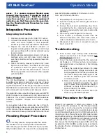
Page 6: ...ake necessary precautions When working on a poten tially flooded camera it is important to use appropriate personal protective equipment to include at a mini mum eye and hand protection 1 Immediately turn off the power to the unit 2 Open the housing by first removing the connector for the device 3 Remove the rear end cap retaining ring Do so by separating the two components using a linear motion I...

Page 7: ...goods under this contract No agent employee or representative of the Seller has any authority to bind Seller to any information representation or warranty concerning the goods sold under this contract and unless an affirmation representation or warranty made by an agent employee or representative is specifically included within this contract it will not be enforceable by Buyer If notice of defect ...

Page 8: ...HD Multi SeaCam Operator s Manual 8 Appendix A Tristate Input Camera Control ...

Page 9: ...ate A and Tristate B Each control pin has three valid states pulled high HI pulled low LO or undriven open OPEN These states are mapped to a menu navigation direction with Tristate A controlling UP and DOWN and Tristate B controlling LEFT and RIGHT Simultaneously pulling both tristate pins low is mapped to a SELECT function as summarized in the table below Pulling both pins high can be used to ret...

Page 10: ...25 1 60000 FLICKER SENS UP OFF X2 X8 OFF AGC 0 20 10 BACKLIGHT OFF OFF HLC LEVEL 0 20 BLC H POS 0 20 V POS 0 20 H SIZE 0 20 V SIZE 0 20 WDR WEIGHT LOW MIDDLE HIGH DAY NIGHT MODE AUTO COLOR B W EXTERN COLOR SMART IR OFF ON OFF AGC THRES 0 20 10 AGC MARGIN 0 20 10 DELAY LOW MIDDLE HIGH LOW N D LEVEL 0 20 7 D N LEVEL 0 20 5 WHITE BALANCE AUTO AUTO AUTO ext PRESET NOT AVAILABLE MANUAL KELVIN LOW MIDDL...

Page 11: ... OFF LOW MIDDLE HIGH OFF DEFOG OFF OFF MODE AUTO MANUAL LEVEL LOW MIDDLE HIGH SHADING OFF OFF ON OFF WEIGHT 0 100 PRIVACY OFF OFF ON ZONE NO 0 15 ZONE DISP OFF ON H POS 0 60 V POS 0 40 H SIZE 0 60 V SIZE 0 40 Y LEVEL 0 20 CR LEVEL 0 20 CB LEVEL 0 20 MOTION DETECT OFF OFF ON SENSITIVITY 0 20 WINDOW TONE WINDOW USE WINDOW ZONE DET H POS 0 60 DET V POS 0 40 DET H SIZE 0 60 DET V SIZE 0 40 ALARM OFF O...

Page 12: ... OFFSET 0 20 USER 8 FULL COMP OUTPUT MODE 1080P 720P 1080P COLOR SPACE HD CbCr YUV SD CbCr HD CbCr FRAME RATE 30FPS 25FPS 60FPS 50FPS 30FPS CVBS NTSC PAL NTSC LANGUAGE English Chinese Chinese s Japanese Korean English COLORBAR OFF ON OFF RESET NOT AVAILABLE EXIT ...

Page 13: ...ight collected on the imager This will slow the effective refresh rate of the video increase latency and add artifacts to dynamic scenes such as motion blur and increased pixel noise Enabling SENS UP is generally not useful for subsea applications 1 5 4 BACKLIGHT Backlit Image Compensation The BACKLIGHT menu offers mechanisms for compensating for back lit scenes and is not often useful in subsea i...

Page 14: ...the brightness of the image in dark areas and lowers the brightness in light areas to compress the dynamic range of an image into the displayable picture This effect can enhance visibility in high contrast lit scenes but is disabled by default in the factory settings 1 5 8 9 DEFOG The DEFOG filter is a digital effect that employs contrast stretching to help improve visibility of objects in cloudy ...

Page 15: ... these settings from their default values 1 5 10 5 FRAME RATE Users can select the video frame rate for a given Output Mode either 30 or 25 frames per second 60 and 50 frames per second rates are not currently supported for either OUTPUT MODE 1 5 10 6 CVBS The CVBS analog video output can be configured for either NTSC or PAL formats and frame rates 1 5 10 7 LANGUAGE Select between English Chinese ...

Page 16: ... camera using the two Tristate inputs hold Tristate A and Tristate B high for 5 seconds After 5 seconds the camera will undergo a brief reset sequence during which the camera video outputs will be disabled and there will be no image available After the successful factory reset the output video drivers will be enabled again and the camera will be reset to the factory default settings This process t...

Reviews: