background image

System Setup


SuperDVR & TD Series Cards

User  Manual


30 


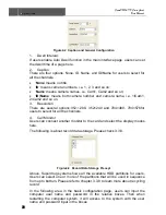
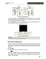
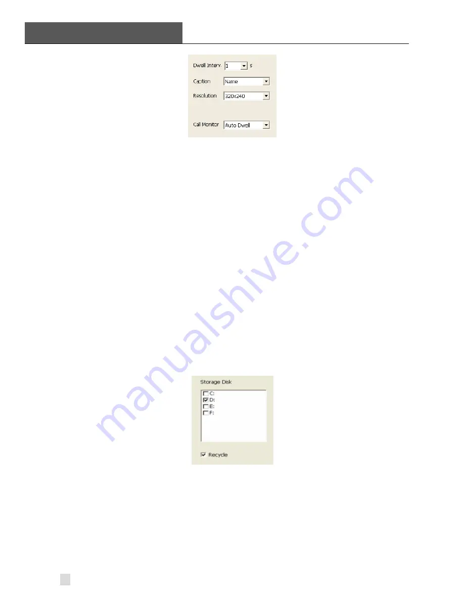
Figure4-2  Caption and General Configuration 

1. Dwell 

Interval. 

If users enable Auto Dwell function in the main interface page, users can set 
the dwell time of a page here. 

2. Caption 
There are four options, None, ID, Name, and ID/Name for users to select for 
all the channels. 

  ‘

None

’ means no title; 

  ‘

ID

’ means camera numbers, i.e. 1, 2, 3 and so on; 

  ‘

Name

’ means camera names, i.e. Cam1, Cam2 and so on; 

  ‘

ID/Name

’ means both camera number and camera name, i.e. 1/Cam1, 

2/Cam2 and so on. 
3. Resolution 
There are several options:352

×

288

352×240 and 704×480

704×576for 

users to select for all the channels.   

4. Call 

Monitor 

Users can connect another monitor to the card and select the display modes 
here. 

The following is about record data storage. Please check 3.3.8. 


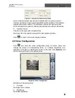
Figure4-3  Record Data Storage Precept 

Above, Superdrug system shows all the available HDD partitions for users. 
Users can select one or more of the partitions that will be used in sequence 
from up to bottom. Please refer to chapter 3.3.8 to learn more about recycling 
record. 

In the following area in the basic configuration page, users can input the 
computer user name and password in the relative boxes. Then when 
restarting the computer system, it will access to the system with the user 
name and password input in the boxes.   

Summary of Contents for 82-13110

Page 1: ...Owner s Manual 1 800 543 4330 82 13110 4 Channel PCI DVR Card 650 Congress Park Dr Centerville OH 45459...

Page 2: ...6 TD3216 Card Hardware 11 2 1 7 TD3308 Card Hardware 11 2 1 8 TD3316 Card Hardware 13 2 1 9 TD3101 USB Card Hardware 14 2 1 10 TD3104 USB Card Hardware 14 2 1 11 TD4104 4404L 4404 Card Hardware 15 2...

Page 3: ...er 42 5 P T Z Control 43 6 Record Search Playing Back 46 6 1 Record Search 47 6 2 Playing Back and Control 47 6 3 Other Functions 50 6 3 1 Record File Backup 50 6 3 2 Delete Record Files 51 6 3 3 Capt...

Page 4: ...WebCam server or RPB server 79 Appendix 2 4 Other Questions 79 Appendix 2 4 1 Why computer display doesn t work and why I can t access window system 79 Appendix 2 4 2 Why I can t find the recorded fil...

Page 5: ...igure2 22 Multi Card Connection 16 Figure2 23 TD4116 Video Capture Card 16 Figure2 24 Audio Connector and Pins Definition 17 Figure2 25 Video Pins Definition 17 Figure2 26 TD4316 4416L Video Capture C...

Page 6: ...rol 47 Figure6 4 Play Speed Controller 48 Figure6 5 Record Files Browser 48 Figure6 6 Multiple Channels Playing Back Control 49 Figure6 7 Channel Configuration Dialog for Single Channel Playing Back M...

Page 7: ...3 Fig 7 33 Scam Shortcut icon in System Menu 73 Fig 7 34 Main Layout of Scam 74 Fig 7 35 Configuration Login Information 74 Fig 7 36 Log in Successfully 74 Fig 7 37 Alarm Setting 75 TABLES Table1 1 TD...

Page 8: ...systems educational systems armed forces and so on TD4408 TD4408L and TD4416L cards In this manual you will learn how to install the hardware and driver software and how to setup the systems of this...

Page 9: ...unction In case SuperDVR driver or windows system is frozen the watchdog will restart the computer and login SuperDVR system again automatically One PC support 1 to 4 cards of the same model the maxim...

Page 10: ...0 XP VISTA DirectX 9 0 Table1 1 TD3004 TD3216 Series Cards System Requirements NOTICE Notice motherboards listed below which has passed the test can work well with TD3004 TD3216 GIGA GA 8IRXI Intel 84...

Page 11: ...nimum 1700MHz Motherboard Intel 845 865 915 series HDD 80G minimum RAM 256M minimum VGA GeForce2 GeForce4 FX5200 ATI Rage128 OS Windows 2000 SP4 above 2003 SP2 above XP SP2 above VISTA DirectX 9 0 USB...

Page 12: ...316 4416L 4416System Requirements Motherboards and VGA cards listed below which have passed the test can work well with TD4116 in Windows XP system Motherboard VGA card COLORFUL C975X MVP ATI HD2400 N...

Page 13: ...inimum 2 0G minimum OS Windows 2000 2003 XP VISTA DirectX 9 0 Table1 8 TD4108 4308 4408 4408L System Requirements 1 3 System Specifications Format PAL NTSC Resolution TD3004 3008 3016 3116 3216 3101 3...

Page 14: ...gure2 1 TD3004 Video Capture Card Pin Port Define Interpret 1PIN 5V Power Source 5V 2PIN ALARM_COM Alarm COM 3PIN ALARM_NC Alarm Normal Close 4PIN ALARM_IN1 Alarm Input 1 5PIN ALARM_NO Alarm Normal Op...

Page 15: ...1PIN 5V Power Source 5V 2PIN ALARM_COM Alarm COM 3PIN ALARM_NC Alarm Normal Close 4PIN ALARM_IN1 Alarm Input 1 5PIN ALARM_NO Alarm Normal Open 6PIN ALARM_IN2 Alarm Input 2 7PIN GND Ground 8PIN ALARM_I...

Page 16: ...4 Pin24 Alarm_out8 Alarm Output 8 Pin5 Alarm_in5 Alarm Input 5 Pin25 Alarm_out9 Alarm Output 9 Pin6 Alarm_in6 Alarm Input 6 Pin26 Alarm_out10 Alarm Output 10 Pin7 Alarm_in7 Alarm Input 7 Pin27 Alarm_...

Page 17: ...ut2 Alarm Output 2 Pin38 5V Power Source 5V Pin19 Alarm_out3 Alarm Output 3 Pin39 Not Used Not Used Pin20 Alarm_out4 Alarm Output 4 Pin40 Not Used Not Used Table2 3 Pins Definitions of TD3016 Card 2 1...

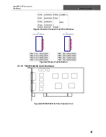
Page 18: ...s User Manual 2 Hardware Installation 11 2 1 6 TD3216 Card Hardware Figure2 10TD3216 Video Capture Card Figure2 11Pins Definitions of TD3216 Video Capture Card 2 1 7 TD3308 Card Hardware Figure2 12TD3...

Page 19: ...erpret Pin Port Define Interpret Pin1 Alarm_in1 Alarm Input 1 Pin21 Pin2 Alarm_in2 Alarm Input 2 Pin22 Pin3 Alarm_in3 Alarm Input 3 Pin23 Pin4 Alarm_in4 Alarm Input 4 Pin24 Pin5 Alarm_in5 Alarm Input...

Page 20: ...IN12 AUDIO5 PIN3 AUDIO6 PIN13 AUDIO7 PIN4 AUDIO8 PIN14 AUDIO9 PIN5 AUDIO10 PIN15 AUDIO11 PIN6 AUDIO12 PIN16 AUDIO13 PIN7 AUDIO14 PIN17 GND PIN8 AUDIO15 PIN9 AUDIO16 PIN10 AUDIO1 PIN26 Figure2 16Audio...

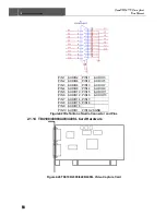
Page 21: ...VIN 16 PIN8 GND Figure2 17Video Pins Definition 2 1 9 TD3101 USB Card Hardware Figure2 18 TD3101 USB Video Capture Card 2 1 10 TD3104 USB Card Hardware Figure2 19TD3104 USB Video Capture Card NOTICE...

Page 22: ...04 4404L 4404 Video Capture Card PIN1 VIDEO 1PIN9 GND PIN2 GND PIN10 AUDIO 1 PIN3 VIDEO 2PIN11 AUDIO 2 PIN4 GND PIN12 AUDIO 3 PIN5 VIDEO 3PIN13 AUDIO 4 PIN6 GND PIN14 NULL PIN7 VIDEO 4PIN15 GND PIN8 G...

Page 23: ...ction 2 1 12 TD4116 Card Hardware Figure2 23TD4116 Video Capture Card P2 DFD202 F 26 R T 1 2 3 4 5 6 7 8 9 10 11 12 13 14 15 16 17 18 19 20 21 22 23 24 25 26 28 27 PIN1 AUDIO2 PIN11 AUDIO3 PIN2 AUDIO4...

Page 24: ...Audio Connector and Pins Definition J1 GiL G 8P S3T2 E 1 2 3 4 5 6 7 8 J2 GiL G 8P S3T2 E 1 2 3 4 5 6 7 8 PIN1 VIN 1 PIN2 GND PIN1 VIN 5PIN2 GND PIN3 VIN 2 PIN4 GND PIN3 VIN 6PIN4 GND PIN5 VIN 3 PIN6...

Page 25: ...UDIO6 PIN13 AUDIO7 PIN4 AUDIO8 PIN14 AUDIO9 PIN5 AUDIO10 PIN15 AUDIO11 PIN6 AUDIO12 PIN16 AUDIO13 PIN7 AUDIO14 PIN17 PIN8 AUDIO15 PIN18 PIN9 AUDIO16 GND PIN10 AUDIO1 PIN19 26 Figure2 27Definition of A...

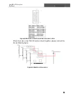
Page 26: ...PIN3 VIDEO 2PIN11 AUDIO 2 PIN4 GND PIN12 AUDIO 3 PIN5 VIDEO 3PIN13 AUDIO 4 PIN6 GND PIN14 NULL PIN7 VIDEO 4PIN15 GND PIN8 GND Figure2 29Definition of Audio and Video Connector s Pins When there are so...

Page 27: ...on the motherboard Before installing the Video Capture Card hardware in PCI port of the motherboard make sure you ve installed Microsoft DirectX 9 0 Then turn on the computer the system will remind y...

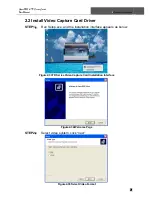
Page 28: ...21 2 2 Install Video Capture Card Driver STEP1 Run Setup exe and the installation interface appears as below Figure2 33TD Series Video Capture Card Installation Interface Figure2 34Welcome Page STEP2...

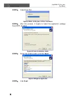
Page 29: ...ver first Figure2 36Rate of Progress of Driver Installation STEP4 After this process it begins to install the application package SuperDVR as below Figure2 37Select Installation Folder STEP5 Select th...

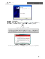
Page 30: ...Restart the computer and launch the surveillance program Figure2 40Shortcut of SuperDVR NOTICE When you install the driver software on Microsoft VISTA system you need select the option as below figure...

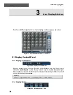
Page 31: ...play Control Panel Figure3 2 Display Control Panel Display control panel includes Display Mode buttons and disk free space indicator Auto Dwell button Every button has its built in indicator light Whe...

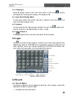
Page 32: ...ick system will save 32 pictures to the default folder on disk c path 3 1 6 Urgent Record Click system will be recorded and saved all the cameras 3 2 Login Click and login window appears Input the use...

Page 33: ...ing 1 Time Stamp By selecting the options the record date time message appears in the record file images 2 Switch By selecting the options users can turn on corresponding cameras In case there is no c...

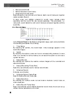
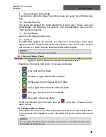
Page 34: ...ese audio signals NOTICE Users can select more than one record mode 3 3 3 Record Status Panel Figure3 6 Record Status Panel Alarm Output Status Panel Meanings of indicator light colors in row one is a...

Page 35: ...r certain channels in Motion Detection Configuration Configure working schedule for certain channels in Schedule Configuration 3 3 7 Schedule Record Users can set working schedule for all kinds of rec...

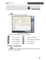
Page 36: ...finitions of the buttons in Figure4 1 are as below Basic Configuration Schedule configuration Video configuration Motion Detection Configuration Alarm Configuration P T Z Configuration User Configurat...

Page 37: ...2 288 352 240 and 704 480 704 576for users to select for all the channels 4 Call Monitor Users can connect another monitor to the card and select the display modes here The following is about record d...

Page 38: ...browse This item is the save path of capture files Users can fill in the specific save path for their capture pictures Click to return to the main display interface 4 2 Video Configuration Click and e...

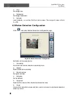
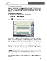
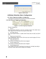
Page 39: ...and enter Motion Detection Configuration page Figure4 6 Motion Detection Configuration Definition of the setup items 1 Sensitivity Users can set motion detection sensitivity here 2 Speed Motion detect...

Page 40: ...hedule configuration options Every channel has three kinds of record modes i e schedule record motion detection record and sensor alarm record We provide users to set schedules from Sunday to Monday s...

Page 41: ...if the alarms have been triggered and also select how long the buzzer rings 2 Pre Alarm Record Users can select whether to enable alarm pre record and also pre record time 3 Big Screen Holding Time Th...

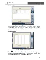
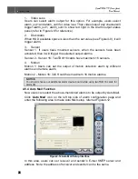
Page 42: ...4 and CAM5 for Sensor2 then once the sensor is activated CAM1 CAM4 and CAM5 will begin to record Users can also select the voltage high and low for alarm signals 4 5 3 Alarm Output Figure4 11Alarm Out...

Page 43: ...utput alarms Sensor 2 Sensor 16 TwoTD4116 cards have maximum 16 sensors 4 Motion Motion 1 Users can set the output of motion detection alarm by different alarms and remote alarm Motion 2 Motion 16 32C...

Page 44: ...E For every alarm event only one picture will be sent 4 6 E map Configuration E map is used to show full geographic range covered by the whole monitoring system in the form of map An E map has the fea...

Page 45: ...Map to save the current map A gray map icon can be drawn to the corresponding position in the map on the right and set it as a sub map of the current map or click the gray map icon on the left by righ...

Page 46: ...f picture frame is 833 678 3 On this interface click camera by right key to display the spot and the 3316 card does not support this function temporarily 4 If Auto Show is set in case that E map pops...

Page 47: ...a certain camera and select a port number in P T Z Protocol Setup refer to Figure4 18 and then set corresponding parameters in the area below Figure4 19P T Z Serial Port Setup 1 Port Users can set por...

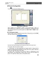
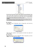
Page 48: ...uration area refer to Figure4 20 and click Edit and enter Edit User area as below Figure4 21User Password and Rights Edit Users can edit user s password and rights here but not the user name The syste...

Page 49: ...onfiguration the normal user can conduct this right NOTICE Administrators can change and authorize rights to Power users and Normal users but they cannot change or authorize other administrators right...

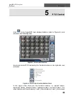
Page 50: ...gure5 1 P T Z Control Interface Users can control P T Z devices by the function buttons on the right side see as below Figure5 2 P T Z Control Function Buttons Panel In the upper circle there are five...

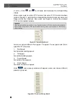
Page 51: ...er pressing left mouse button on any function button in P T Z Control Function Buttons Panel refer to Figure5 2 PTZ device starts moving when user releases it PTZ device stops moving Figure5 3 Speed A...

Page 52: ...ple Preset points In case users select preset1 preset2 and preset3 for group1 preset1 preset2 and preset3 will be automatically accessed in sequence after users select group1 for auto scout Figure5 5...

Page 53: ...the SuperDVR Main Display Interface refer to Figure3 1 and access to the following areas Figure6 1 Search and Playback Interface This interface is divided into 4 parts i e record search area record pl...

Page 54: ...arch by date range from Jan 1st 1971 till now B Search in backup file and original file C Search by record mode This is useful when user wants to look through some important events Users can select on...

Page 55: ...rowser The upper bar shows the hours in a whole day Click the bar and it will be magnified 10 times therefore users can see the detailed time marks When searching for a certain section of the file use...

Page 56: ...ation Dialog for Single Channel Playing Back Mode Users can select one channel from all the available channels for playing back In case user needs to play back 4 channels at the same time then click a...

Page 57: ...stem In case user needs to play back 16 channels at the same time then click and the following channel configuration window will appear as below Figure6 10Channel Configuration Dialog for 16 channel P...

Page 58: ...cted in an area by the time interval In C area users can set backup path Click Start to backup files 6 3 2 Delete Record Files Click and the following window will appear Figure6 12Delete Recorded File...

Page 59: ...ttings Figure6 13Color Control Panel When in the single channel playing back pause mode click and the following window will appear as below Figure6 14Capture Multiple Images in Sequence Select path an...

Page 60: ...ess Print in the print preview window users can print the image directly 6 3 4 Image Zoom in out When in single channel playing back state the zoom control icons will appear Select and click on the ch...

Page 61: ...6 Record Search Playing Back SuperDVR TD Series Cards User Manual 54 Figure6 18Example zoomed out Figure6 19Example zoomed in...

Page 62: ...LAN network input the SuperDVR server address in IE browser the end users can get high quality real time image from the server and also control the P T Z devices 7 1 Remote Surveillance Server Configu...

Page 63: ...er not any client software installed And it supports Win XP and vista Input the IE client server IP address in Internet Explorer and selected install ActiveX control then the following figure appears...

Page 64: ...on near Focus button to have long focus Click button near Focus button Zoom button Click button near Zoom button to zoom in the locale picture of this camera Click button near Zoom button to zoom out...

Page 65: ...bandwidth Users can select the stream according to their bandwidth Table 7 1 the function of the main interface buttons Click the right mouse in the main interface a sub menu will appear Open Stream C...

Page 66: ...use Stop Adjust the speed of playing back Users can select suitable play speed in needed Playing back backup Back up record data of server end Users can click Backup enter into the below interface Fig...

Page 67: ...selected channels if users select a certain channel click Select this channel then just this channel be selected only Users can click Clear this channel to clear that selected channels Return to prev...

Page 68: ...records The following are the definitions of the color bar Manual Record Events Schedule Record Events Motion Detection Record Events Sensor Alarm Record Events The ruler on top of the bar shows the h...

Page 69: ...ans camera numbers i e 1 2 3 and so on z Name means camera names i e Cam1 Cam2 and so on z ID Name means both camera number and camera name i e 1 Cam1 2 Cam2 and so on 2 Live audio Supports one channe...

Page 70: ...can select whether to open the computer buzzer if the alarms have been triggered also select how long the buzzer rings 2 Full screen alarm Users can select whether channel will be full screen when ala...

Page 71: ...ting the check box record time will be displayed on the screen when playing back the record 4 Net quality There are five options to choose from lowest lower medium higher and highest Higher picture qu...

Page 72: ...camera name in the left Camera group firstly Click icon and brush on the weekday schedule to add time click icon and click on the weekday schedule to delete time If click users could copy the setting...

Page 73: ...g to different record triggering methods users can set three kinds of record modes z Manual record z Schedule record z Motion record Users can use multiple cameras to record every camera works separat...

Page 74: ...cting storage disk Tick off Recycle check box users can set whether to continue recording to cover the earliest video file when the disc storing video files is full If click users could copy the setti...

Page 75: ...e setting of this channel to any other selected channel 7 4 7 EMAIL Configuration Click icon and access to Email configuration interface Fig 7 21 Email configuration 1 Mail server setup Fig 7 22 Mail...

Page 76: ...iver s E mail Address E Mail from Sender s E mail Address Subject E mail Subject Users can select Set Mail Internal check box to set email send time such as 5 seconds 10 seconds and so on 3 Attachment...

Page 77: ...ommunication protocol of P T Z device B Port Users can set serial port number C Address Communication address of P T Z device 2 Serial port setup Users should firstly enable the P T Z control function...

Page 78: ...could copy the setting of this channel to any other selected channel 7 5 Mobile Surveillance 7 5 1 Introduction to Mobile Surveillance In SuperDVR system the mobile surveillance can be realized by co...

Page 79: ...60 OS7 0s NOKIA Nokia N 95 S60 OS9 2 Table 7 1 Mobile Phone of Supporting Mobile Surveillance 7 5 2 Client Configuration of Windows Mobile Server configuration on SuperDVR needs to be set before the f...

Page 80: ...ndow will pop up after downloading is finished Fig 7 31 Confirmation Information Window Step4 Click OK the system reminds of whether to install the Webcam Fig 7 32 Installing Configuration Information...

Page 81: ...y to users mobile phone whenever their made other operations in the background Fig 7 35 Configuration Login Information HttpPort server side software to set the http port number the default port numbe...

Page 82: ...or vibration tips that users want to be informed when an unusual occurs in remote site Volume adjust the sound Back light background light for Normal open Note By default the mobile phone didn t do a...

Page 83: ...em Enabled Hardware Acceleration and DirectX Acceleration Hardware Acceleration STEP1 Right click the mouse on the desktop then select Properties Setting Advanced Trouble Shooting STEP2 Drag the accel...

Page 84: ...ers can select the percent of used disk space to set up disk shortage alarm You can input percent manually or choose the selectable given items such as 25 50 and 75 to set up For example if selecting...

Page 85: ...s about relatively lower than the theoretic value Appendix 2 2 8 Why I can t select more channels to backup Please draw the mouse in the channel selection area or utilize Shift and Ctrl key for assist...

Page 86: ...ransmission H 264 codec has not been installed properly please download new version WebCam Slow network speed Appendix 2 3 5 What should I do if the Internet speed is quite slow The more channels open...

Page 87: ...you need delete the files that you don t need or need to make disk defragmenter now Capture card problem Computer hardware system is too outdated Appendix 2 4 5 Why I can t play back Windows media pl...

Page 88: ...01 01 0 0 0 target time the change can be made directly 2 If new time is before the current computer time for example change 2007 01 01 0 0 0 current system time to 2006 01 01 0 0 0 target time first...

Page 89: ...ard But do not connect the Camera yet STEP2 Launch windows STEP3 Windows will come up with Hardware wizard Just click Cancel STEP4 Put the installation CD in and open up SuperDVR folder run the Setup...

Page 90: ...address You can go to this link to find the IP address http lawrencegoetz com programs ipinfo STEP3 Open up the SuperDVR program and go to basic configuration Check and ENABLE Web Camera Service and R...

Page 91: ...address of the Main Computer Data port 1159 and Command port 1160 STEP7 Click OK Now you should be able to view the live video from main computer STEP8 To play back the Video that has been recorded i...

Page 92: ...SuperDVR TD Series Cards User Manual Appendix3 Function Tree 85 Appendix3 Function Tree Appendix 4 1 SuperDVR Function Tree Tree1 SuperDVR Function...

Page 93: ...Appendix3 Function Tree SuperDVR TD Series Cards User Manual 86 Appendix 4 2 System Configuration Tree Tree2 System Configuration...

Page 94: ...SuperDVR TD Series Cards User Manual Appendix3 Function Tree 87 Appendix 4 3 IE Client Function Tree Tree3 IE Client Function...

Page 95: ...Appendix3 Function Tree SuperDVR TD Series Cards User Manual 88 Appendix 4 4 Remote Playback Function Tree Tree4 Remote Playback Function...

Reviews: