6
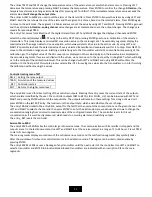
Terminal resistor
According to the RS485 specifications, the last device on the bus must be
ending with a terminating resistor 120R. Plug a jumper on the JP2
connector of the last device on the bus to include the 120R terminating
resistor. In the default configuaration the jumper connector is not
plugged
4.
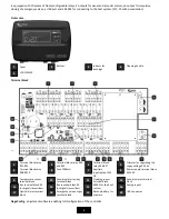
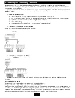
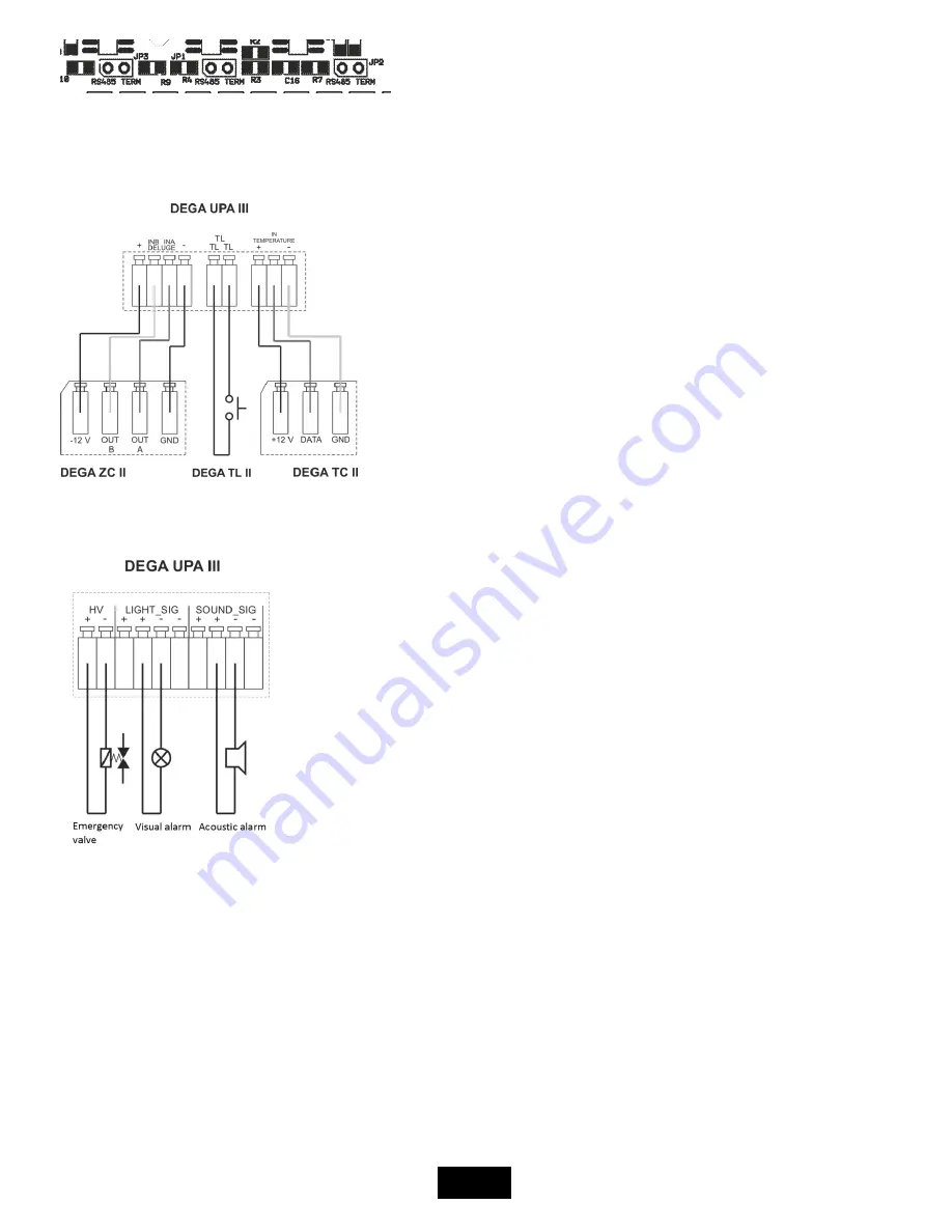
Connecting the temperature sensor, flooding sensor and lay-off button of the beeper
5.
Connecting the visual and acoustic alarms and the emergency valve
6.
Selecting the supply voltage and the maximum current load
Supply voltage 230V AC
The highest current load of the controller is 1,4A. This current serves to power the connected transmitters and the visual and
acoustic alarms, which are connected to the terminal blocks „LIGHT_SIG“ and „SOUND_SIG“.
Example: There are 4 transmitters connected to the controller with a consuption of 60 mA each. The remaining 1,16 A (I=1400-4x60) are
used to supply the visual and acoustic alarms.
Supply voltage 24V DC
The consuption of the controler's electronics is 300mA. Maximal current on terminal blocks „+24V IN/OUT“ is 10A. Maximal
current load on each output on terminal blocks „LIGHT_SIG“ and „SOUND_SIG“ is 4A.


