background image

E

D

I

GB

GO

GO  6 0

6 0

15

Revision - 04

Date 02 - 2006

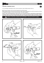
MODALIDAD DE USO

Asegurarse que la pareja tirante/cabeza montada en la remachadora corresponda al formato del inserto a apretar; de otro modo proceder al cambio
de formato. De costumbre la pareja tirante/cabeza montada en la remachadora se entrega con fileteado de M8. Antes de emplear la remachadora
y después de cada cambio de formato hay que efectuar las siguientes operaciones según el formato y el espesor del material a ajustar:
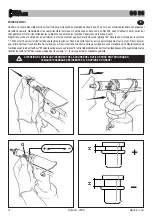
Ajustar la carrera de la remachadora al mínimo, girando la virola “G” en el sentido indicado por el símbolo “–”.
Introducir el inserto en el tirante y presionar ligeramente de manera que el inserto se apriete automáticamente. Asegurarse que la cabeza del
inserto toque la cabeza de la remachadora. Fijar el inserto y para alcanzar el apretamiento según el espesor del material, ajustar la carrera de
la remachadora girando la virola “G” como requerido. Al aumentar de la carrera (rotación de la virola “G” en el sentido indicado por el símbolo “+”)
la distancia “H” entre la cabeza y la deformación del inserto disminuye con una consiguiente aumento de apretamiento.

¡CUIDADO! UN AJUSTE INCORRECTO DE LA CARRERA DE LA REMACHADORA PUEDE CAUSAR

UN APRETAMIENTO DEFECTUOSO DE LOS INSERTOS Y LA ROTURA DEL TIRANTE

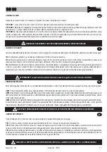
VERWENDUNGSART

Überprüfen, ob das in das Nietwerkzeug eingesetzte Paar Ziehdorn-Kopf der Abmessung der anzuziehenden Blindnietmutter entspricht: sollte
es nicht entsprechen, so ist das Dimensionswechsel vorzunehmen. Normalerweise besitzt das mit dem Nietwerkzeug gelieferte Paar Ziehdorn-
Kopf ein M8-Gewinde. Vor Gebrauch des Nietwerkzeuges und nach jedem Dimensionwechsel sind folgende Eingriffe der Abmessung und der
Stärke des zu vernietenden Materials entsprechend vorzunehmen:
Den Hub des Nietwerkzeuges auf das Minimum einstellen: dazu ist der Ring “G” in Richtung “–” möglichst zu drehen. Die Blindnietmutter auf
den Ziehdorn ansetzen und einen leichten Druck darauf ausüben; dadurch schraubt sich die Blindnietmutter selbsttätig auf den Ziehdorn auf. Sich
vergewissern, daß der Kopf der Blindnietmutter mit dem Kopf der Nietwerkzeuges abschließt. Die Blindnietmutter befestigen und sein Anziehen
an die Stärke des Materials überprüfen. Den Hub des Nietwerkzeuges durch Drehen des Ringes “G” so einstellen, bis das gewünschte Anziehen
erzielt will. Darauf achten, daß der Abstand “h” zwischen Kopf und Verformung der Blindnietmutter bei Vergrößerung des Hubes (Drehung des
Ringes “G” in Richtung “+”) verringert wird, mit darauffolgender Vergrößerung des Anziehens.

ACHTUNG!!! DIE UNKORREKTE EINSTELLUNG DES HUBES DES NIETWERKZEUGES KANN DAS FEHLERHAFTE

ANZIEHEN DER BLINDNIETMUTTER UND DEN BRUCH DES ZIEHDORNES VERURSACHEN!

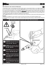
MODALITÀ D’USO

Verificare che la coppia tirante-testina montata sulla rivettatrice sia adeguata alla misura dell’inserto che si vuole serrare; in caso contrario procedere al cambio
di formato. Solitamente la coppia tirante-testina montata sulla rivettatrice in confezione corrisponde ad una filettatura di M8. Prima di utilizzare la rivettatrice
e dopo ogni cambio di formato occorre eseguire le seguenti operazioni in funzione del formato e dello spessore del materiale da serrare:
Regolare la corsa della rivettatrice al minimo, ruotando per quanto possibile la ghiera “G” nel senso indicato dal simbolo“–”. Inserire l’inserto sul
tirante ed esercitare su di esso una leggera pressione; in questo modo l’inserto si avvita automaticamente sul tirante. Assicurarsi che la testa
dell’inserto vada in battuta con la testina della rivettatrice. Fissare l’inserto e verificare il serraggio che questo opera sullo spessore del materiale.
Regolare la corsa della rivettatrice mediante la rotazione della ghiera “G”, in funzione del serraggio desiderato, considerando che all’aumentare
della corsa (rotazione della ghiera “G” nel senso indicato dal simbolo “+”) la distanza “h” tra testa e deformazione dell’inserto diminuisce con
conseguente aumento dell’azione di serraggio.

ATTENZIONE!!! LA REGOLAZIONE NON CORRETTA DELLA CORSA DELLA RIVETTATRICE

PUO’ CAUSARE IL CATTIVO SERRAGGIO DEGLI INSERTI E LA ROTTURA DEL TIRANTE!

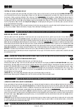
OPERATING INSTRUCTIONS

Make sure that the couple tie-rod/head mounted on your riveting tool is suitable for the insert to clamp; otherwise, change size accordingly. Usually
the riveting tool is supplied with the couple tie-rod/head corresponding to a M8 thread. Before using the riveting tool and after any change of size,
perform the following operations according to the size and thickness of the part to clamp.
Adjust the riveting tool stroke to the minimum by turning the ring nut “G” to “–” marked on the tool. Place the insert on the tie rod and push slightly
on it so as to make it clamp automatically. Make sure the insert head touches the riveting tool head properly. Fasten the insert and in order to ensure
a proper clamping of the material, adjust the riveting tool stroke by turning the ring nut “G” accordingly. By increasing stroke, i.e. by turning the
ring nut “G” to “+”, the distance “h” between head and insert deformation will decrease and clamping will result more effective.

WARNING!!! A WRONG ADJUSTMENT OF THE RIVETING TOOL STROKE

MAY CAUSE A FAULTY CLAMPING OF INSERTS AND MAY BRAKE THE TIE ROD!

Summary of Contents for GO 60

Page 1: ...8 INSTRUCTIONS FOR USE MAINTENANCE NOTICES RIVETTATRICE OLEOPNEUMATICA PER INSERTI M3 M8 ISTRUZIONI USO MANUTENZIONE AVVERTENZE ÖLPNEUMATISCHES NIETWERKZEUG FÜR BLINDNIETMUTTERN M3 M8 BEDIENUNGSANLEITUNG WARTUNG HINWEISE REMACHADORA OLEONEUMATICA PARA INSERTOS M3 M8 INSTRUCCIONES DE USO MANUTENCION ADVERTENCIAS GB E D I F GO 60 ...

Page 2: ... and subsequent amendments and integrations De conformidad con los requisitos esenciales de seguridad previstos por elDPR 459 96 de actuación de las Directivas CEE 89 392 y 91 368 y sucesivas modificaciones e integraciones En conformité aux conditions essentielles de sécurité requises par le DPR 459 96 de mise à effet des Directives CEE 89 392 et 91 368 et modifications et intégrations successives...

Page 3: ...N seite 4 WERKZEUGIDENTIFIZIERUNG seite 9 ALLGEMEINES UND HANDHABUNG seite 9 HAUPTSÄCHLICHE TEILE seite 11 TECHNISCHEN DATEN seite 13 GEBRAUCK DES NIETWERKZEUGS seite 15 WARTUNG UND AUSWECHSLUNG DES FORMATS seite 17 AUFFÜLLEN DES ÖLS DES ÖLDYNAMISCHEN KREISLAUFS seite 19 ERSATZTEILE seite 20 INDICE AVVERTENZE DI SICUREZZA pag 4 IDENTIFICAZIONE DELLA RIVETTATRICE pag 9 NOTE GENERALI E CAMPO DI APPL...

Page 4: ... indiqués dans le chapitre ENTRETIEN Pour le remplissage de l huile il faut utiliser les fluides indiqués dans ce dossier En cas de fuites imprévues de huile au contact de la peau il faut se laver soigneusement avec de l eau et du savon alcalin L outil de pose peut être transporté à main et il doit être remis dans sa boîte après l usage Pour obtenir un bon fonctionnement de l outil nous vous suggé...

Page 5: ...ndschuhe zu verwenden Verwenden Sie nur Ausrüstungen die in der Betriebsanleitung empfohlen sind wenn Sie am Werkzeug Instandsetzungen und Regulierungen durchführen Beim Ölwechsel verwenden Sie nur Öle die den empfohlenen Ölen des Handbuches entsprechen Falls Sie Öl auf die Haut bekommen waschen Sie die mit Wasser und Alkaliseife ab Wir empfehlen das Werkzeug nach Gebrauch in die Kassette zu geben...

Page 6: ...Le désordre peut causer des dommages aux personnes Personne si étranger ne peut utiliser les outils de pose Ilfauts assurerquelestuyauxd alimentation de l air comprimé soient appropriés conformes à l utilisation prévue Ne pas traîner l outil de pose quand il est connecté à l alimentation Le tuyau doit se trouver toujours loin de sources de chaleur ou d objets tranchants Les outils de pose doivent ...

Page 7: ...Dimension ist NehmenSiedasangeschlosseneWerkzeug nie am Druckluftschlauch Das gesamte Werkzeug soll fern von Hitze und schneidenden Teilen gehalten werden Halten Sie das Werkzeug in guter Verfassung und verändern Sie weder Schutzvorrichtungen noch Schall dämpfer Nach Reparatur und oder Einstellung vergewissern Sie sich daß das Sicherheitswerkzeug entfernt wurde Bevor Sie den Druckluftschlauch absc...

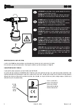
Page 8: ...l équiper du culot de protection suivant la figure ci contre DEGOMETAL n est pas responsable des éventuels dommages occasionnés à l outil personnes ou choses par manque du culot WARNING Before using the tool assemble the protection bottom supplied with the tool as indicated in the picture on side DEGOMETAL has no responsibility for any damages on the tool persons or things caused by lack of the pr...

Page 9: ... das Modell aufweist Falls ein Service notwendig ist lesen Sie die Daten des Schildes ab TOOL IDENTIFICATION TherivetingtoolGO6Oisidentifiedbyalabelshowingthenameofthemanufacturerandmodel Ifanyserviceisrequestedpleasemakereference to data shown on the label NOTAS GENERALES Y AMBITO DE APLICACION La herramienta puede utilizarse sólo para insertos fileteados con rosca de díametro M3 M8 Gracias al si...

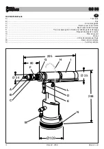
Page 10: ... A Tirant fileté B Tête C Ecrou blocage tête D Bouton poussoir de traction E Bouton poussoir de devissage F Trou pour passage de la broche pour deblocage de l embrayage G Bague de réglage de la course H Etrier de support I Moteur L Orifice de remplissage d huile M Raccord d air comprimé N Culot de protection N ...

Page 11: ...ola de regulación carrera H Enganche balanceador I Motor L Tapón tanque aceite M Conexión aire comprimido N Fondillo de protección HAUPTSÄCHLICHE TEILE A Ziehdorn mit Gewinde B Kopf C Kontermutter fur Kopf D Ziehentaste E Abschraubentaste F Loch zum Einstecken des Zapfens für die Einrückungsfreigabe G Einstellring für den Hub H Balancerhalterung I Motor L Öleinfüllschraube M Druckluftanschluß N Sc...

Page 12: ...m 6 BAR 1450 KG Poids 2 130 KG Température d utilisation 5 50 Valeur moyenne quadratique pondérée en fréquence de l accélération totale Ac à laquelle les bras sont soumis 2 5 M SEC2 ALIMENTATION EN AIR L air d alimentation doit être libre de corps étrangers et d humidité pour sauvegarder l outil d une usure précoce des parties en mouvement il est donc recommandé d utiliser un groupe de graissage e...

Page 13: ...Temperatura de utilización 5 50 Valor medio cuadrático de la aceleración total registrado en frecuencia Ac ejercitado sobre los miembros articulados superiores 2 5 M SEC2 LUFTSPEISUNG Die verwendete Luft darf keine Fremdkörper und Feuchtigkeit enthalten um die Maschine vor dem vorzeitigen Verschleiß der sich bewegenden Teile zu schützen Deshalb ist die Verwendung einer Wartungseinheit für Druckluf...

Page 14: ...t que possible l embout de réglage G dans le sens indiqué par le symbole Présenter l insert sur le tirant et faire une légère pression sur l insert de cette façon il se visse automatiquement sur le tirant Il faut s assurer que la tête de l insert touche la tête de l outil de pose Fixer l insert et en vérifier le serrage sur l épaisseur du matériel à sertir Réglerlacoursede l outildeposeentournantl...

Page 15: ...d mit darauffolgender Vergrößerung des Anziehens ACHTUNG DIE UNKORREKTE EINSTELLUNG DES HUBES DES NIETWERKZEUGES KANN DAS FEHLERHAFTE ANZIEHEN DER BLINDNIETMUTTER UND DEN BRUCH DES ZIEHDORNES VERURSACHEN MODALITÀ D USO Verificarechelacoppiatirante testinamontatasullarivettatricesiaadeguataallamisuradell insertochesivuoleserrare incasocontrarioprocederealcambio diformato Solitamentelacoppiatirante ...

Page 16: ...rs l arrière pour débloquer l embrayage du tirant Avant de dévisser le tirant on doit l extraire doucement FIG 3 4 Toujoursavecl embrayagedébloqué visserleformatdetirantchoisi Terminéleremplacementducoupletirant tête tournerlégèrementletirant même jusqu au moment où l on remarque le déclic d embrayage Ensuite monter la tête correspondante et la bloquer par l embout prévu à cet effet et précédemmen...

Page 17: ...IRE A LA REMACHADORA DIMENSIONSWECHSEL Beim Änderung des Gewindes der zu vernietenden Blindnietmuttern ist das Paar Ziehdorn Kopf auszutauschen Dazu wie folgt vorgehen ABB 1 Die Kontermutter mittels eines handelsüblichen 25mm Gabelschlüssels lockern und den Kopf abnehmen ABB 2 Den Zapfen zur Ausrüstung gehöhend durch die eigens dafür vorgesehene an Kopfträger befindliche Serviceöffnung stecken und...

Page 18: ...rquée Mettre l outil de pose déconnecté en position horizontale enlever le bouchon A en utilisant la clé de 5 mm fournie pendant cette opération il faut soigneusement éviter les éventuels écoulements d huile Ensuite visser dans le logement du bouchon A la burette à soufflet X après l avoir rempli d huile à VISCOSITE 32 En retenant l outil de pose en position horizontale mettre en route l alimentat...

Page 19: ...zata allo smaltimento dei rifiuti AUFFÜLLEN DES ÖLS DES ÖLDYNAMISCHEN KREISLAUFS Das Auffüllen des Öls des öldynamischen Kreislaufs wird nach einer langen Arbeitsperiode jedesmal nötig wenn man eine Abnahme des Hubs bemerkt Bei stillgelegtem NICHT LUFTZUGEFÜHRTEN horizontalen Nietwerkzeug den Stöpsel A durch den Ausstattung gehörenden 5mm Inbusschlüssel entfernen Dabei achten Sie darauf daß das Öl...

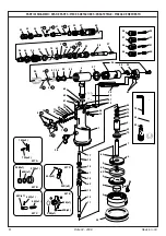
Page 20: ...9 90 25 24 44 35 91 76 75 69 92 B 66 65 B 21 B 68 34 36 48 47 46 45 53 52 51 50 43 54 42 C 41 40 C 97 67 39 37 82 60 C 74 55 23 61 79 18 80 72 A 20 D 78 81 16 A 59 D 17 62 1 64 70 71 86 5 83 7 4 84 9 3 8 2 95 88 89 10 87 14 75 15 77 82 13 12 11 96 98 72A x2 16A x2 KIT A KIT B KIT C KIT E 20D x2 59D x3 KIT D 92B x1 65B x1 21B x1 42C x1 40C x1 60C x1 63E x3 99E x1 32E x1 ...

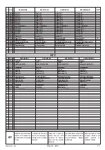
Page 21: ...course Regleranhubnutmutter 39 711799 1 Pomello regolazione corsa Stroke adjusting knob Poignée réglage course Drehknopf für Hubeinstellung 40C 711800 1 Molla disinnesto tirante Spring disengagement tie rod Ressort désembrayage tirant Feder Zugbolzenauskupplung C 41 711801 1 Cannotto porta tirante Head carrying tie rod Tête porte tirant Zugbolzenträger 42C 711802 1 Innesto per tirante Clutch for t...

Page 22: ...9 90 25 24 44 35 91 76 75 69 92 B 66 65 B 21 B 68 34 36 48 47 46 45 53 52 51 50 43 54 42 C 41 40 C 97 67 39 37 82 60 C 74 55 23 61 79 18 80 72 A 20 D 78 81 16 A 59 D 17 62 1 64 70 71 86 5 83 7 4 84 9 3 8 2 95 88 89 10 87 14 75 15 77 82 13 12 11 96 98 72A x2 16A x2 KIT A KIT B KIT C KIT E 20D x2 59D x3 KIT D 92B x1 65B x1 21B x1 42C x1 40C x1 60C x1 63E x3 99E x1 32E x1 ...

Page 23: ...oussoir Kit drucktaste 20D 711705 2 Pulsante Push button Bouton poussoir Drucktaste 59D 711726 3 Spina 2x20 UNI 1707 Pin 2x20 UNI 1707 Goupille 2x20 UNI 1707 Stift 2x20 UNI 1707 78 710376 2 OR 2 9 P O Ring 2 9 P O Ring 2 9 P O Ring 2 9 P 79 710918 2 OR 2 5 P O Ring 2 5 P O Ring 2 5 P O Ring 2 5 P 80 710919 2 OR 2 4 P O Ring 2 4 P O Ring 2 4 P O Ring 2 4 P 81 710003 2 OR 5 052 P O Ring 5 052 P O Ri...

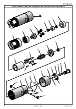
Page 24: ...24 Date 02 2006 Revision 04 PARTI DI RICAMBIO SPARE PARTS PIECES DETACHEES ERSATZTEILE PIEZAS DE REPUESTO MOD AM 0001H 1 11 12 25 26 15 16 17 18 19 20 21 21 21 23 22 23 27 13 14 3 4 2 5 6 7 8 21 9 10 24 ...

Page 25: ...ent 624ZZ Lager 624ZZ 15 71345174 1 Otturatore destro Right obturator Obturateur droit Rechter Verschluß 16 71345175 1 Otturatore sinistro Left obturator Obturateur gauche Linker Verschluß 17 716277 2 Grano M4x4 UNI 5927 Dowel M4x4 UNI 5927 Cheville M4x4 UNI 5927 Dübel M4x4 UNI 5927 18 71345167 1 Corpo Body Corps Körper 19 71C00127 1 OR 1 5x9 5 O Ring 1 5x9 5 O Ring 1 5x9 5 O Ring 1 5x9 5 20 71C00...

Page 26: ......

Page 27: ......

Page 28: ...LES VIS A BOIS ET VIS AUTO PERCEUSES GOUJONS A BAGUE OUTILS DE POSE POSTES A SOUDER Classique aveugle Éclaté Fermé Grande plage de serrage Cannelé A fentes Cranté Goujon clou expansé Haute résistance A2 A4 CI AR Avec ou sans collerette Vissage rapide et fiable Fixation murale Manuels oléopneumatiques TIG MIG et d autres modèles ZI 1ère Avenue 5ème Rue B P 443 06515 CARROS Cedex 1 FRANCE Tél 33 0 4...

Reviews: