


B-Series Air Velocity Sensors USER GUIDE 67500MN00-A01
B-Series Air Velocity Sensors USER GUIDE 67500MN00-A01
1
B
-
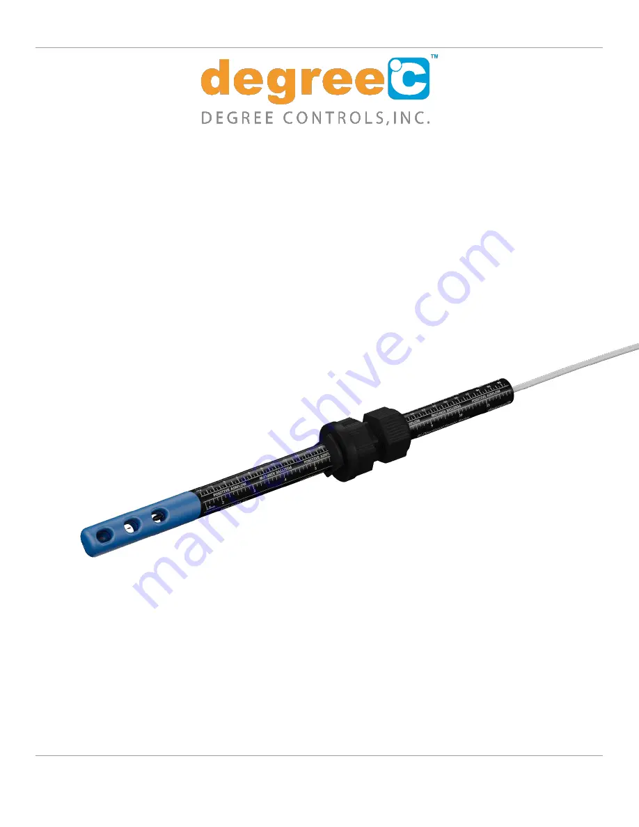
Series Air Velocity Sensors
User Guide
DEGREE CONTROLS, INCORPORATED
18 Meadowbrook Drive
Milford, New Hampshire 03055 USA
Degree Controls, Inc. © Copyright 2018, all rights reserved.
Information in this document is subject to change without notice.
Windows® is a registered trademark of Microsoft Corporation • All other trademarks are property of their respective owners.


