

Rooster™ Monitor100 USER MANUAL
Rooster™ Monitor100 USER MANUAL 62310MN000-A04
1 of 33
User Manual
This is proprietary information of Degree Controls Inc., contents are protected under US copyright laws © Degree
Controls, Inc. 2020.
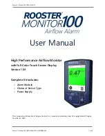
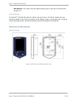
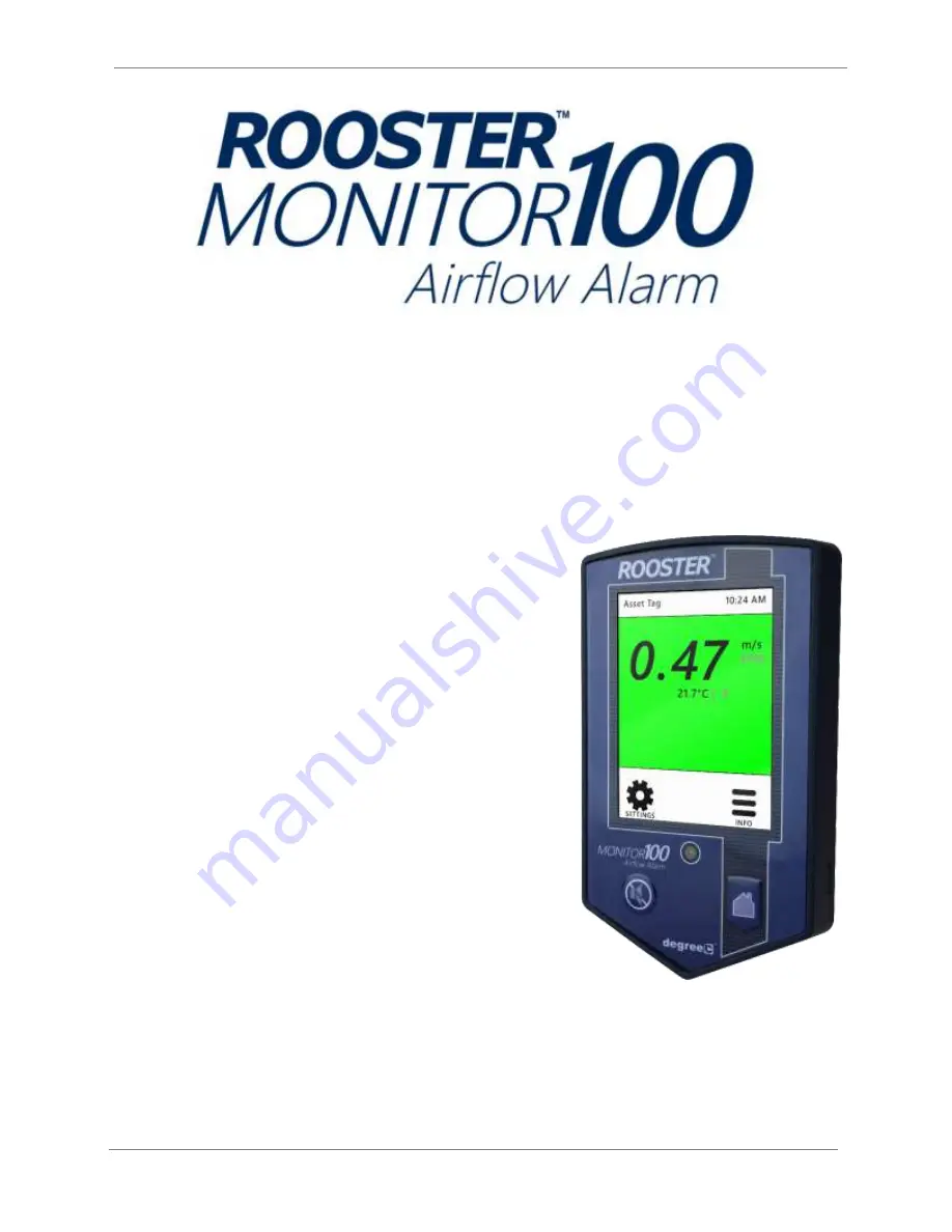
High Performance Airflow Monitor
with Full-Color Touch Screen Display
Version 1.04
Complete Kit includes:
o
Alarm Module
o
Choice of Sensor Type
o
Power Supply


