


Rooster™ Monitor100 USER MANUAL
Rooster™ Monitor100 USER MANUAL 62310MN000-A04
13 of 33
4.
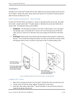
Secure back plate.
5.
Mount the sensor. See below for sensor installation descriptions with different sensor
styles.
6.
Feed power and sensor wire harnesses through the opening(s) and make connections to
the Rooster
TM
Monitor100 alarm module. Make any other optional connections to the
alarm module.
7.
Align top of alarm module with tabs on back plate, and secure in place with captive
screw at bottom of alarm module.
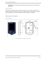
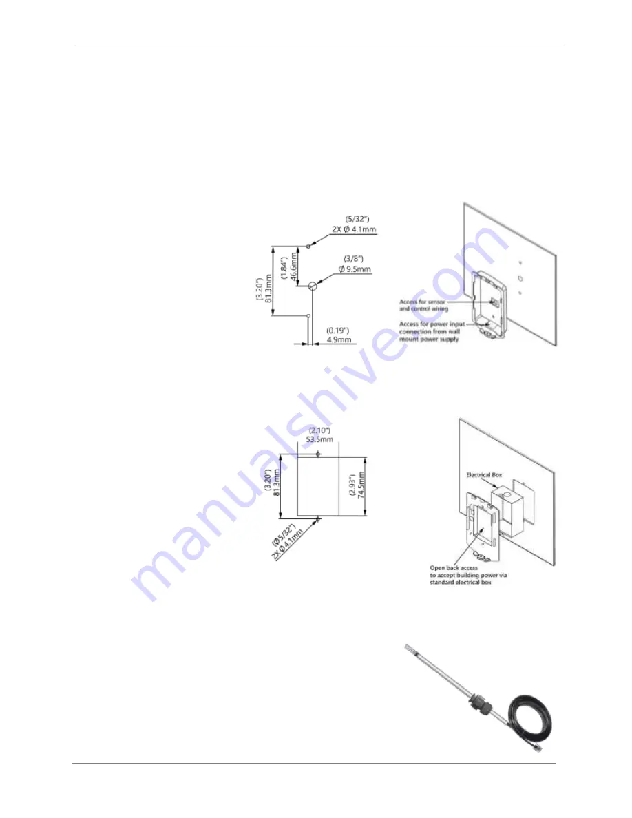
Figure 7 Wall Mount Back Plate Mounting
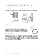
Figure 8 Semi-Flush Back Plate Mounting
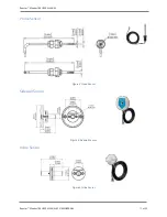
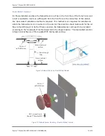
Probe Sensor
The Probe sensor should be located in the duct system in the
best laminar (stable) flow possible. The sensor should be
placed at least two duct diameters away from duct elbows and
constrictions, and follow ASHRAE best practices.
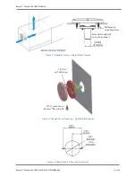
Probe sensor installation steps:
1.
Drill 16mm [5/8”] hole.


