4
2. Air-termination rods with concrete block
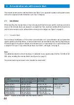
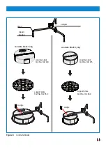
The isolated air-termination rods listed below (see Table 1) are supposed to protect roof su per struc tu res
and can be adjusted to roof inclinations up to max. 10 degrees.
2.1 Installation
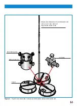
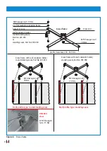
When installing the concrete block, it has to be observed that the braces and the con ti nuous concrete
recess of the concrete blocks are aligned in a straight line. Thus, maximum stability of the brace frame
and the air-termination rod is achieved when driving in the wedges (see Figure 3 on page 5).
2.1.1 Concrete block
For mechanical stabilisation of the tubular air-termination rod / air-termination rod and protection
against possible wind load effects, a concrete block has to be installed on every bracing. Depending on
the total length of the relevant tubular air-termination rod / air-termination rod, a concrete block with
a weight of 8.5 kg or 17 kg is installed per brace (see Table 1 and Figure 3 on page 5).
Note:
For additional protection of roof sheetings, it is advisable to use support plates, Part No. 102 050 or 102
060, when installing the concrete blocks (see Figure 3 on page 5).
The air-termination system must not be installed on metal roofs!
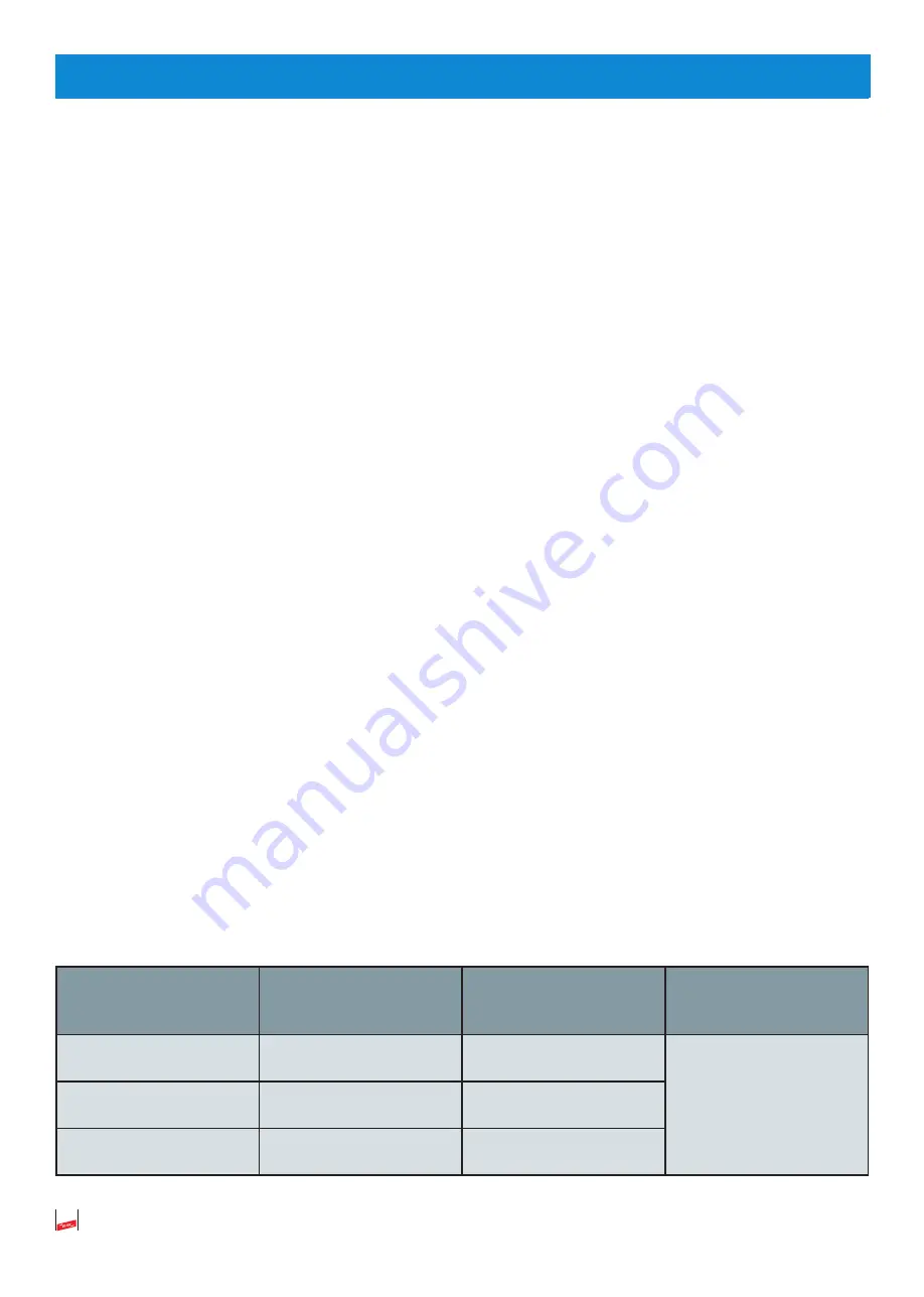
Complete
isolated air-termination
rod
Tubular air-termination
rod/ Air-termination rod
Ø 22 / 16 / 10 mm
Concrete block
per brace
Tripod
Part No. 105 525
Length: 2500 mm
Part No. 103 233
Length: 2500 mm
Part No. 102 075
1x concrete block 8.5 kg
Part No. 105 501
Brace length / radius
R = 320 mm
Part No. 105 530
Length: 3000 mm
Part No. 103 243
Length: 3000 mm
Part No. 102 010
1x concrete block 17 kg
Part No. 105 535
Length: 3500 mm
Part No. 103 535
Length: 3500 mm
Part No. 102 010
1x concrete block 17 kg
Table 1
Isolated air-termination rods from 2500 to 3500 mm
Summary of Contents for 102 010
Page 15: ...15 Notizen ...
Page 31: ...15 Notes ...


