Ermittlung der zu tauschenden
SPD's
min. 2 Sek.
push sync
push
siehe Pkt. 7.3
RFID
signal
DEHNr
ecor
d
DRC LC M3
DEHNr
ecor
d
DRC LC M3
DEHNr
ecor
d
DRC LC M3
ja
push
sync
0
9
check
check
check
push
sync
Display
DEHNr
ecor
d
DRC LC M3
DRC MCM:
Configuration
OK
OK
6
4
OK
OK
push show
push sync
USB
RS-485
RT=On
MCM
RT=On
bus
adress
A
+/-
B
-/+
+/-
A
-/+
B
A
ddre
ss
No
. o
f m
oni
tor
ed
S
PD'
s
OK
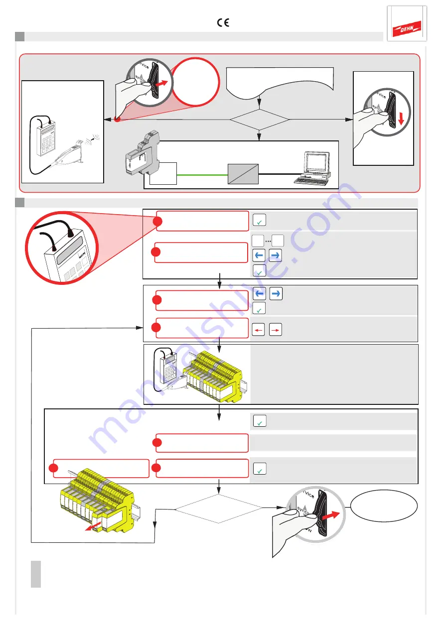
Open selected menu
0
9
Enter bus/MCM address and number of
SPDs
Switch between bus address and
number of SPDs
Confirm configuration
Check SPD
ADR=xy nn*SPD
DRC MCM:
Check / Search
Configuration
ADR=xy SPD=nn
7.1 Testing SPDs using the DRC LC M3+ handheld reader (operating mode: DRC MCM)
ADR=xy SPD=NN
Check SPD --> OK
Snap sensor onto the SPD to be
tested and do not remove it during
the testing process.
Testing in progress
Confirm testing process:
- LifeCheck OK, successful
- Replace SPD, repeat testing process
LifeCheck OK
ADR=xy SPD=NN
Replace SPD
ADR=xy SPD=NN
-- Check --
Please wait !
No
all SPDs
tested ?
01 - nn
via
DRC LC M3/M3+
SPD test via
DRC LC M3/M3+
handheld reader
≥ version 1.1.02
PC
show button
Determination of
SPDs
to be
replaced
see 7.1
min. 2 sec.
see 7.3
DRC MCM XT
Program end
Activate the DRC MCM XT
or in case of bus onnection
only one DRC MCM XT at
the bus as Master.
Note:
When testing SPDs via the DRC LC M3 handheld reader, please observe operating manual BA 1670/V 1.1.01
"Extension for Stationary Monitoring Device DRC MCM XT"
.
Start testing
Select a menu
and open it
Select SPD to be tested
(positions number)
Remove
faulty SPD!
min. 2 sec.
Yes
min. 2 sec.
Deactivate
MCM
Master
7. Determination of SPDs to be replaced
Status determination via PC using the
Status Display software
see 7.2
page 11


