
20
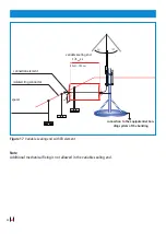
5. Installation
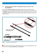
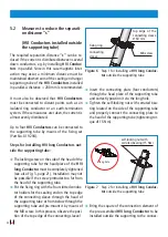
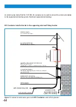
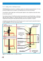
5.1 Installing HVI long Conductors in the supporting tube
Before installing the supporting tube, insert the fixed head piece of the pre-assembled
HVI long Con-
ductor
into the supporting tube and fix it (see also Fig. 5, page 21).
The following steps must be observed
Â
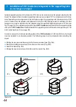
Unscrew the locking screw of the head piece (M8 x 25 mm) at the head of the supporting tube.
Â
Insert the
HVI long Conductor
from below into the supporting tube. To this end, the compressive
strength of the integrated EB spring element must be overcome. The conductor can be inserted and
removed several times. To contact the head piece, insert the
HVI long Conductor
into the suppor
-
ting tube as far as it will go and hold it there.
Â
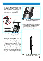
The locking screw (M8 x 25 mm) is firmly tightened again using a tightening torque of 15 Nm. Thus,
the head piece is fixed in the supporting tube and is electrically connected (capable of carrying light
-
ning currents). Make sure that there is a sufficient distance (about 7 mm) between the screw head
and the supporting tube after tightening the locking screw. The adhesive coating of the screw only
hardens after about 5 minutes so that the screw can be correctly positioned and tightened during
this period. After the adhesive coating has hardened, the screw must be replaced by a new one if
the screw is removed.
Â
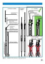
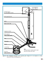
Check whether the
HVI long Conductor
is properly fixed in the supporting tube (see Fig. 5). Proper
installation can be verified by slightly pulling the conductor at the point where the conductor leaves
the supporting tube.
Â
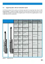
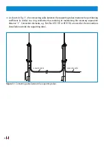
Depending on the construction of the installation, the relevant air-termination tip/air-termination
rod must be installed before or after the supporting tube has been installed.
Â
Insert the air-termination tip/air-termination rod from above into the head of the supporting tube
and tighten the two locking screws (M8 x 16 mm/M8 x 10 mm) using a tightening torque of 15 Nm.