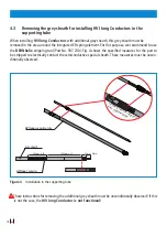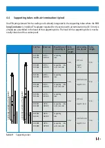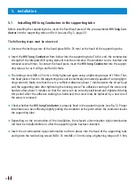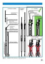
23
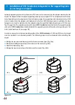
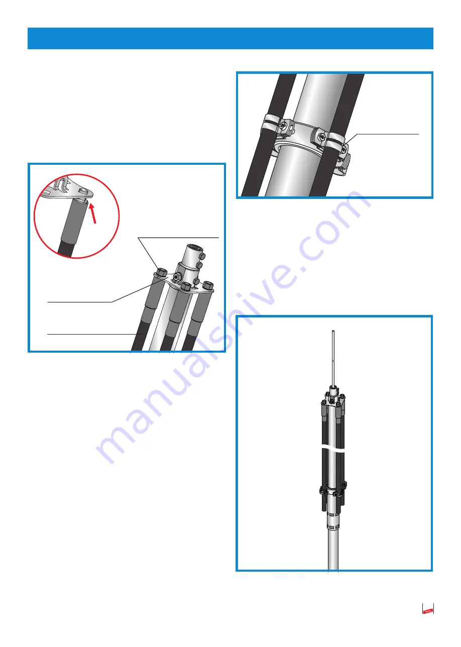
ting plate and mechanically and electrically
(capable of carrying lightning currents) connect
the nut (M12) and the Nord Lock washer. Ensu
-
re that the square hole is correctly positioned
and use a tightening torque of 25 Nm.
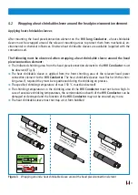
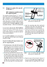
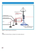
Figure 8
Step 3 for installing a
HVI long Conduc-
tor
outside the supporting tube
Â
Install the
HVI long Conductor
on the sup
-
porting tube and correctly connect it to the
slotted cleats of the fixing ring. Ensure stra
-
ight conductor routing on the supporting tube.
If required, readjust the position of the fixing
ring. Firmly fix the fixing ring by means of the
M8 screw (tightening torque of 15 Nm). When
using a
HVI
long Conductor
or a pre-assemb
-
led HVI
Conductor with additional grey sheath,
the outer grey sheath in the area around the
slotted cleats must be removed to contact the
black sheath. The black sheath must not be cut
in.
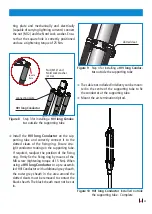
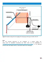
Figure 9
Step 4 for installing a
HVI long Conduc-
tor
outside the supporting tube
Â
The cable ties included in delivery can be moun-
ted in the centre of the supporting tube to fix
the conductor at the supporting tube.
Â
Mount the air-termination tip/rod.
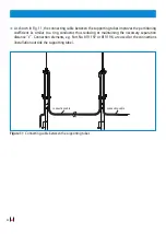
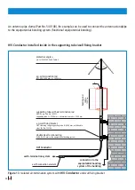
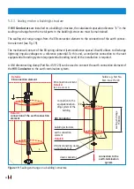
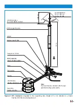
Figure 10 HVI long Conductor
installed outside
the supporting tube - Complete
Nut (M12) and
Nord Lock washer
(25 Nm)
connecting plate
HVI long Conductor
square
hole
slotted cleat

