
25
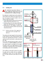
5.3 Sealing end
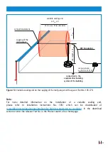
The calculated separation distance “s"
from conductive/earthed parts must be
maintained in the sealing end range.
No conductive or earthed parts such as metal con-
ductor holders, structural parts, reinforcement, etc.
(see 5.3.3, page 32) may be installed in the sea-
ling end range, for example:
Â
At the supporting tube between the head piece
and EB connection element (see 5.3.1)
Â
Variable sealing end on the ring conductor/cap-
ping of the roof parapet (see 5.3.2, page 28)
Â
Sealing end on the building's structure bet-
ween the EB connection element and the earth
connection element.
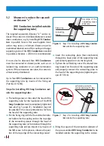
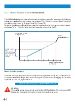
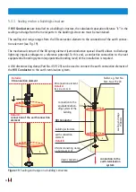
5.3.1 Sealing and rang at the supporting
tube based on the example of an
antenna
The sealing end range ranges from the connection
of the head piece to the EB spring element integ-
rated in the supporting tube (see Fig. 12, detail A
and B) and can be assumed to run along the entire
GRP tube.
Due to the mechanical spring contact, acting as
an EB element, the
HVI Conductor
(semiconduc-
tive special sheath) is connected to the suppor-
ting tube. To this end, the supporting tube must be
conductively connected with the next equipoten-
tial bonding system of the installation.
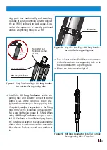
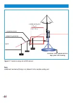
The conductive connection between the suppor-
ting tube and the metallic antenna standpipe is
established by means of e.g. a pipe clamp (Part
No. 105 360) (mechanical and electrical connec-
tion).
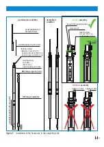
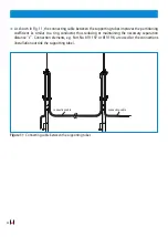
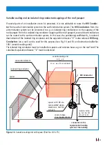
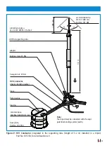
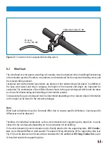
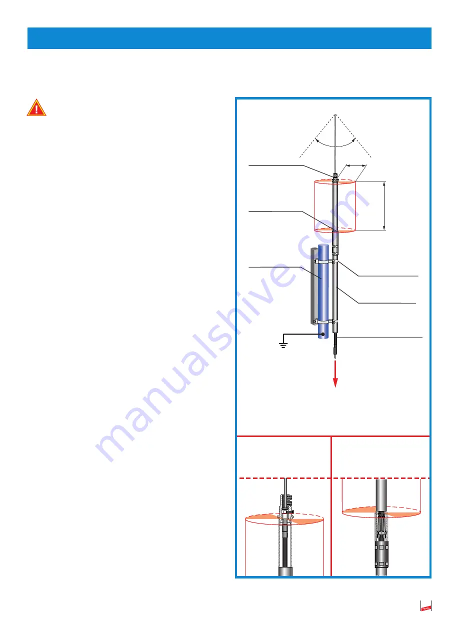
Figure 12
Sealing end range in the supporting tuber
sealing and
range
Detail A:
connection of the
head piece
Detail B:
EB spring element
connection of
the head piece
Detail A
s
α α
EB spring element
Detail B
antenna
standpipe
pipe clamp
supporting tube
HVI long Conductor
connection to the
equipotential bon-
ding system of the
installation
connection to the
earth-termination
system


