

36
8. Conductor installation
The entire
HVI Conductor
must be installed in the protected zone of the air-termination system of the
external lightning protection system and must not be connected to parts of the air-termination system,
down conductor or structural parts carrying lightning voltage.
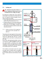
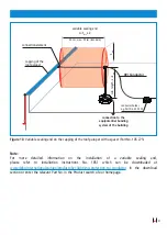
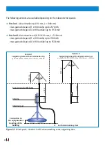
An exception can be made if the separation distance ”s” at the crossover of the
HVI Conductor
and
the part carrying lightning voltage (air-termination system, capping of the roof parapet, down conduc
-
tor) is ≤ 0.35 m (air) or ≤ 0.7 m (solid material). In this case, the sheath of the
HVI Conductor
can be
connected to the part carrying lightning voltage.
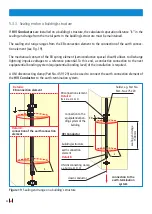
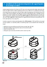
Downstream of the sealing end range, the
HVI Conductor
must be fixed at intervals of ≤ 1 m.
The fixing screws of metal conductor holders must be tightened with max. 5 Nm, the fixing screws of
plastic conductor holders with max. 2 Nm.
If a
HVI Conductor
is installed in the structure, existing protection measures, e.g. fire barriers, must be
observed.
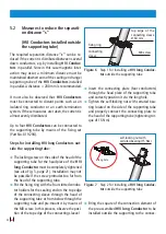
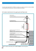
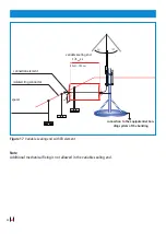
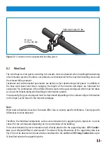
8.1 Additional connection of the external cable sheath for equipotential bon-
ding
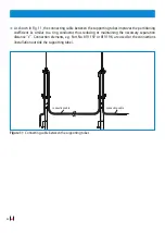
In case of crossovers or parallel conductor routing towards earthed metal installations such as cap
-
pings of the roof parapet, cable racks or pipelines, it is advisable to connect the black sheath of the
HVI Conductor
to the equipotential bonding system. This is a complementary equipotential bonding
measure.
Connections can be made with EB clamps, Part No. 405 020. This EB connection does not have to
be capable of carrying lightning currents. Conductor cross-sections ≥ 4 mm
2
(copper) or conductor
cross-sections with the same conductivity must be used.
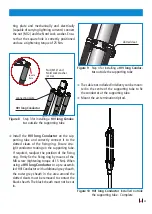
When using
HVI Conductors
with grey sheath, the grey sheath must be removed to contact the black
semiconductive sheath underneath it. The black sheath must not be cut in.


