


18
Digital IN
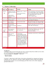
Selbsttest / Self-test
VCSD aus / VCSD off
Status
Fehlerstatus / failure m
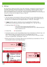
6. VCSD aus
Bei der intensiven Fehlerortung (IFO) sind von KKS-Fachkräften umfangreiche messtechnische Unter-
suchungen notwendig, damit Umhüllungsfehler (sog. Fehlstellen) an Pipelines lokalisiert werden
können. Hierbei sollte der VCSD hochohmig sein, damit die Rohrleitungskapazitäten durch den
VCSD nicht verfälscht werden und somit die „Taktung“der Messung beinflussen. Die Aktivierung des
Manuell-Aus erfolgt über den digitalen Eingang „Digital IN“.
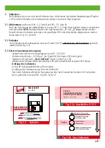
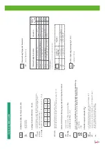
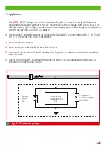
Eingang Digital IN:
Dient der gezielten Abschaltung des Gerätes per Fernzugriff, um eine mögliche Beeinflussung,
z.B. während einer intensiven Fehlerortung (IFO) durch KKS-Fachkräfte auszuschließen oder um
ein sicheres An- und Abklemmen zu ermöglichen (Brücke “VCSD aus“, siehe Fig.6c)
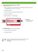
Ist nicht galvanisch getrennt, deshalb muss hier ein potentialfreier Schließerkontakt
(siehe Fig. 6a) zur Aktivierung verwendet werden (Schaltdaten: 9 V, 1 mA, max. 100 Ω)
Kontakt geschlossen
VCSD-Aus
- ohne externe Spannungsversorgung: Manuell-Aus
- mit externer Spannungsversorgung: Manuell-Aus mit Überwachung einer
festen Schwelle von 50 V
Kontakt offen
Standardbetrieb
Die Aktivierung kann aus allen Standardbetriebsarten heraus (betriebsbereit, Überwachungs- und
Ableitbetrieb) erfolgen und wird über die LED vor Ort angezeigt (siehe Fig. 6 b).
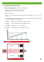
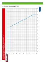
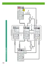
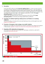
Der 4 ... 20 mA-Ausgang verbleibt fest bei 4.0 mA, wenn das Gerät extern versorgt wird (siehe
auch die Prinzipdarstellung „Betriebsmodi“ Seite 24).
Während des Manuell-Aus erfolgt die Überwachung einer festen Ansprechschwelle von 50 V nur
bei anliegender externen Spannungsversorgung!
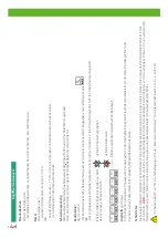
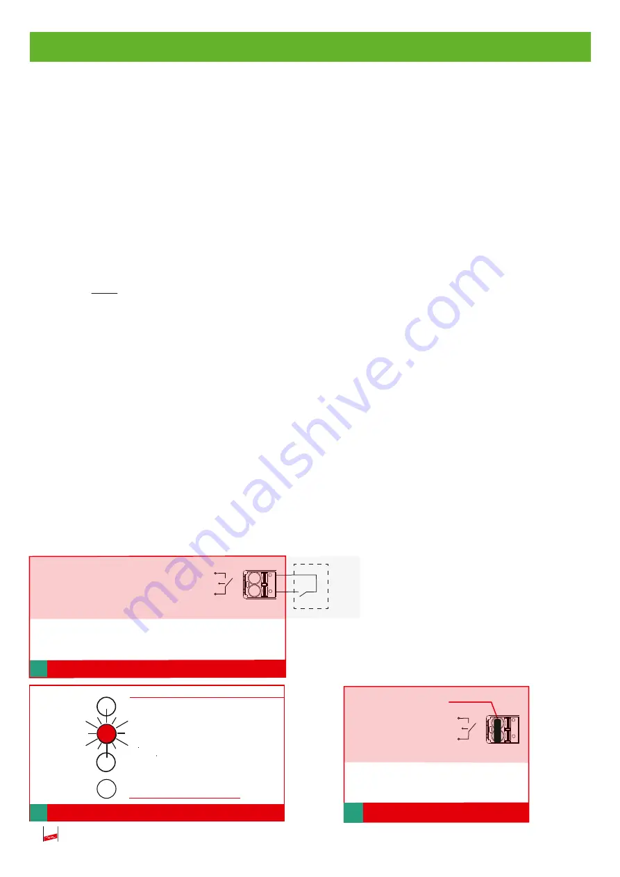
Digital IN
Anschlussquerschnitt: max 2,5mm
2
Fig. 6a Externer Relaiskontakt
Externer
Anschluss
z.B.
Leitwarte
Brücke
Fig. 6b Manuell-Aus
Fig. 6c Brücke „VCSD aus“