
19
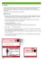
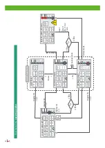
Digital IN
Analog OUT
(I
out
= 4 ...20 mA DC)
A
20
30
Fig. 7
max. 2.5 mm²
Digital OUT
10
40
0
4
8
12
16
20
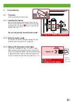
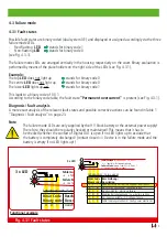
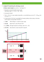
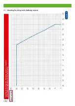
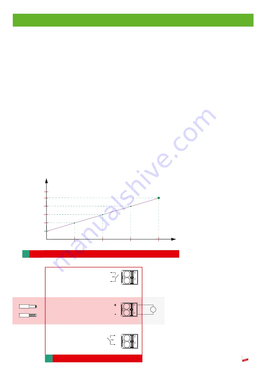
7. Analog OUT (monitoring the discharge current)
4-20 mA current output
(see also Fig. 7 and diagram 7):
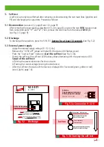
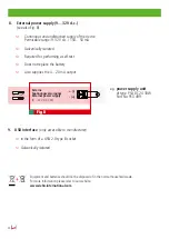
Required to operate the external power supply.
Permissible range: 9…32 V d.c. / 150…50 mA
Galvanically isolated
The 4…20 mA d.c. output signal corresponds to an actual discharge current of 0…40 Arms, that
is 0.4 mA / 1 A.
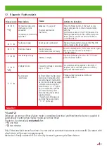
An alarm value of 22.8 mA is transmitted for remotely signalling a failure mode at the device
which requires on-site operator intervention.
< 4mA
Wire breakage or no external power supply
4.0 mA
Monitoring or switch-off mode VCSD
4 – 20 mA
Discharge mode with a discharge current of 0…40 A
22.8 mA
Fault indication, on-site intervention required!
Diagram 7
[A
rms
]
[mA
d.c.
]
22,8
22.8


