background image


11 


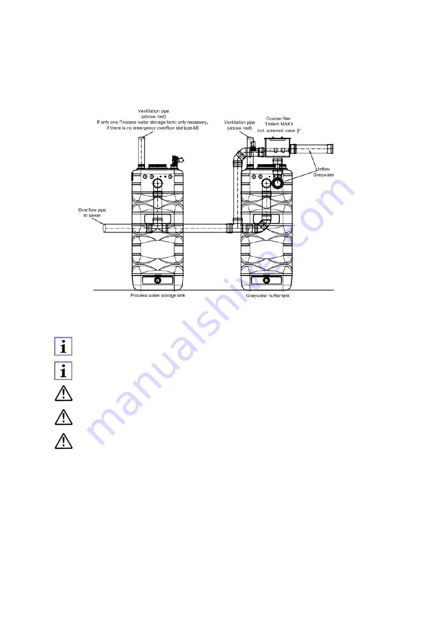
The overflow connections of the coarse filter and those of the greywater and process water storage tanks are designed to be flat 

pipe  connections  and  must  be  connected  with  the  drain.  You  must  ensure  that  no  greywater  can  flow  into  the  process  water 

storage tank when connecting the overflow connections from the greywater and process water storage tanks with the drain. 


Figure 4: Connection of the overflows ports 


We recommend installing a separate ventilation line for the greywater buffer tank. The greywater buffer tank has 

a 2” female tank screw available for this reason. 


We recommend installing a siphon in the drain overflow to avoid any bad smells. 


The drain connection or pump system must be able to securely drain the maximum drinking water feed volume 

(see 3.3). 


Make sure the overflow line to the sewer/pumping system has the same nominal width as the overflow connec-

tion (no cross-section constriction!). 


The installation room is at risk of flooding if the overflow connection is not attached to the drain. 


5.4. 

Overflow of the tanks 

Summary of Contents for 813335

Page 1: ...Watermanager GWM 500 inhouse Greywater treatment for re use of process water Installation and commissioning manual Valid from Firmware version GWM 500_V 5 43 Last updated 18 03 2019 ...

Page 2: ...escription 5 3 1 Functional description 5 3 2 Process water quality 5 3 3 Technical specifications 6 3 4 Scope of delivery 6 3 5 Structure 7 3 6 Intended use 7 3 7 Improper use 8 4 Transport 8 5 Installation Assembly 9 5 1 Installation room 9 5 2 Installation of the tanks 9 5 3 Connection of the coarse filter 9 5 4 Overflow of the tanks 11 5 5 Air compressor and filtrate lines 12 5 6 Installation ...

Page 3: ...greywater inflow 23 6 4 Step 3 commissioning to automatic operation 24 6 5 Extended periods of downtime 25 7 Repairs 26 7 1 Inspections 26 7 2 Maintenance 27 8 Errors Troubleshooting 29 8 1 Errors displayed at the control unit 29 8 2 Pressure surges in drinking water line 29 8 3 Odours in the installation room at the consumers 29 9 Disposal 29 10 Declaration of Conformity 30 ...

Page 4: ...r any Software Update please consider the new corresponding operation manual for the control unit Never exceed the permitted limits of use stated in the documentation with regards pressure temperature etc Follow all the safety advice and handling instructions in this manual Instructions displayed directly on the system must be heeded and must be kept in a completely legible condition This applies ...

Page 5: ... entirety at the Watermanager GWM s place of use only sufficiently qualified and authorised personnel assemble the Watermanager GWM commission it repair it and carry out maintenance on it these personnel are regularly instructed in all the relevant issues of occupational safety and environmental protection as well as ensuring that they have read and understood the manual and specifically the safet...

Page 6: ... persons who have been trained instructed and authorised for this purpose If necessary training can be provided the manufacturer supplier at the re quest of the operator Training sessions for the system must only be carried out under the supervision of technical profession als The relevant authorisations of personnel must be clearly specified by the operator in the form of a user guide In addition...

Page 7: ...delivery conditions and terms of sale of DEHOUST shall apply Any warranty and liability claims for personal or material damage are void if they can be attributed to one or more of the following causes Improper use of the Watermanager GWM Improper assembly commissioning operation and maintenance of the Watermanager GWM Non compliance with the instructions in the manual regarding transportation stor...

Page 8: ...aining biomass ultrafiltration If there is no process water available the Watermanager GWM automatically switches to drinking water operation If needed drinking water is automatically feed into the process water storage tank in accordance with DIN EN 1717 AB All unit processes are micro electronically monitored by the central control unit and managed in a fully automated manner Faults are shown by...

Page 9: ...C Mains voltage 230 V AC 50 Hz 16 A Power consumption without pres sure increase watt 200 Empty weight kg 110 Booster pump Delivery rate Delivery height Connection Power consumption 5 5 m h 48 m 1 male 1 100 230 V All shown details may vary depending to specific project details Pre assembled Watermanager GWM 500 consisting of Trident coarse filter Greywater buffer tank BMT unit Process water stora...

Page 10: ...ment may arise if the Watermanager GWM is used improperly Only operate the Watermanager GWM in a technically flawless state Do not operate the Watermanager GWM in a partially assembled state The Watermanager GWM is used to treat slightly contaminated domestic wastewater from showers bathtubs and washba sins The Watermanager GWM may be operated up to a maximum water temperature of 40 C Heed the inf...

Page 11: ...ntrated lyes and acids medical mud baths pharmaceuticals medication foaming water additives silicones resins solvents colouring agents flocculants Do not fill the media utilities of the system with flammable media Do not put the casing and tank under mechanical strain e g by stacking objects on them or using them as steps Do not make any external changes to the equipment casing and tanks Casing co...

Page 12: ...way of the supply tank The tanks should be installed on the basis of the separate set up diagram Each individual tank is labelled and marked accord ingly Ensure that all tanks are installed at the same level to avoid any malfunctions during the system operation The connection sizes of the coarse filter can be found in the specifications see 3 3 Before it can be connected with the coarse filter inl...

Page 13: ...ction of the backflushing line of coarse filter MAX I and MAX II We recommend installing a shut off valve and a detachable screw The flow pressure to the back flushing line must conform to the specifications see 3 3 Make sure the overflow line to the sewer pumping system has the same nominal width as the overflow connec tion no cross section constriction 5 3 2 Backflushing line of the coarse filte...

Page 14: ... recommend installing a separate ventilation line for the greywater buffer tank The greywater buffer tank has a 2 female tank screw available for this reason We recommend installing a siphon in the drain overflow to avoid any bad smells The drain connection or pump system must be able to securely drain the maximum drinking water feed volume see 3 3 Make sure the overflow line to the sewer pumping ...

Page 15: ...y on the bracket Connection Connection width at tank Material Colour Air compressor mal thread PVC flex tube ø19 mm Red Filtrate effluent male thread PVC flex tube ø13 mm blue Figure 5 Connect hose lines for ventilation and filtrate When installing the PVC hoses ensure that there are no constrictions kinks which can prevent the free flow of water and air The greywater buffer tank BMT unit must not...

Page 16: ...onnect the other side of the HDPE pipe with the corresponding quick connector at the tank Connect the electrical quick connector with the corresponding connector at the tank Place the booster pump vertically on the tank bottom to avoid malfunctions Don t transport lift or hang the booster pump by the electric cable Figure 6 connection of HDPE pipe and booster pump Figure 7 installation of booster ...

Page 17: ...14 Figure 8 connection of HDPE pipe and tank connector Figure 9 electrical connection of the booster pump ...

Page 18: ...em Install a pressure reduced in front of the system if necessary so it is guaranteed that no more than 5 bar of primary pressure is fed in from the drinking water network We recommend installing a shut off valve a detachable screw and an external fine water filter We recommend installing a cold water meter The feed volumes of the drinking water feed must be within the range of the stated flow pre...

Page 19: ...r pipe with extern booster pump station Connect the suction line in a de energised state No forces must be applied to the threaded sleeve connection of the system We recommend installing a shut off valve and a detachable screw We recommend installing a cold water meter in the pressure line We recommend to install an expansion vessel in the pressure line after the booster pump station Heed the inst...

Page 20: ... of the process water storage tank into the installation room This free overflow is required to protect the drinking water line in accordance with DIN EN 1717 Figure 13 Type AB emergency overflow 5 9 Emergency overflow due to Type AB drinking water feed The installation room must have a suitable floor drain sump to securely drain away the overflowing water in case of back flooding via the emergenc...

Page 21: ...0 i e sockets with earthing terminals The electrical network onto which the equipment is connected must have a residual current operated circuit breaker RCCB in accordance with DIN EN 60335 2 41 VDE 0700 Always connect other external energy consumers e g pressure boosters to a separate voltage source Figure 14 electrical connections at the bottom side of the control unit 1 20X4 Filtrate pump 2 20X...

Page 22: ...ure 15 Electrical connection of coarse filter greywater buffer tank and process water storage tank 5 10 1 Electrical connection of coarse filter greywater buffer tank BMT unit and pro cess water storage tank ...

Page 23: ...ed to the control unit Please follow below steps Switch off control unit from power supply Remove the 6 allen screws size 2 at the control unit to remove cover plate Insert alarm cable through corresponding cable connection at the bottom side of the control unit please see Figure 14 Connect alarm cable at following outputs at Crouzet controller O2 Please see Fehler Verweisquelle konnte nicht gefun...

Page 24: ...ply Remove the 6 allen screws size 2 at the control unit to remove cover plate Insert alarm cable through corresponding cable connection at the bottom side of the control unit please see Figure 14 Connect extern alarm cable at following inputs at Crouzet controller 24VDC and I1 Please see Figure 17 Close control unit by mounting the cover plate use the 6 allen screws Switch on control unit Figure ...

Page 25: ...lding works are still being carried out in the building step 1 We recommend installing a bypass of the greywater line directly into the sewer for this period Only upon commissioning of step 2 should the greywater inlet line be fixed to the system Before commissioning the Watermanager GWM you must ensure the following points The Watermanager GWM is electrically connected to all safety equipment acc...

Page 26: ...ined maxi mum filtrate drain see sticker attached directly to the tacosetter Please heed chapter 0 for manual set up of the fil tration capacity IX Switch into mains water operation Mains water by pressing the function key A at the control unit X Open a process water consumer e g toilet flush tap Close the process water consumer when water is discharged without air pockets XI The system is ready t...

Page 27: ...nd the process wa ter storage tank is not completely filled up III One off manual set up of the filtration flow rate on the Tacosetter of the BMT unit according to the predefined maxi mum filtrate flowrate see sticker attached directly to the Tacosetter Control the filtration flowrate by visible check at the Taccosetter Please see Figure 18 IV If necessary de aerate once again each membrane filter...

Page 28: ...m biological capacity During this time a reduced biological cleaning capacity can occur during the treatment process Weak re sidual scents of shampoo soaps etc may be subjectively noticed in the process water If the downtime of the system is longer than 4 weeks then we recommend a supporting inoculation of microbiology with dry bacteria when the treatment process is recommenced 6 5 Extended period...

Page 29: ...o the backwash for impermeability and function To do this directly activate and disable the solenoid valve in manual mode see Fehler Verweisquelle konnte nicht gefunden werden in the firmware set up Time frame Quarterly Check the solenoid valve to the drinking water feed for impermeability and function To do this open the process water con sumer and wait until the fill level in the process water s...

Page 30: ...he maintenance intervals After a run time of 16 000 operating hours approx 20 months of operation the message Maintenance see operation manual GWM8 1 is shown on the control unit display A contracting party or DEHOUST has to carry out the maintenance and to reset the operating hours meter The filtration performance of the BMT membrane filter depends on the greywater composition the real daily trea...

Page 31: ... instructions of the maintenance log for greywater systems Disconnect the Watermanager GWM from the electricity grid during maintenance and repair work Heed the operation manual GWM as well Heed the manual for BMT membrane filter exchange and software update as well ...

Page 32: ... tank must not fall so low that the pressure booster is switched to dry run protection If the pressure booster still switches to dry run protection then the pressure side must also be reduced The oxygen supply by the air compressor for biological treatment is too low or possibly interrupted Please check the hose connections see 7 1 4 and operating parameters for air compressor filtration see opera...

Page 33: ...ehoust greywater usage Type designation Watermanager GWM 500 Applied standards EN 292 1 EN 292 2 EN 55014 1 EN 55014 2 EN 60204 1 DIN EN 50 081 Part 1 DIN EN 50 082 Part 1 DIN EN 60335 DIN 1988 Part 4 DIN EN 1717 The following operating conditions and ambient conditions must be implemented The appliance is designed for the control regulation and operation of a greywater treatment system The instru...

Reviews: