1. General information
1.1. Warnings, legal information and safety.................................................................................................. 4
1.1.1. Warnings and notes ......................................................................................................................4
1.1.2. Legal information and disclaimer ..................................................................................................4
1.1.3. Safety issues ................................................................................................................................ 4
1.1.4. Electrostatic discharge awareness ............................................................................................... 4
1.1.5. Factory settings ............................................................................................................................ 5
1.2. About the Designer's Reference Handbook........................................................................................... 5
1.2.1. General purpose ...........................................................................................................................5
1.2.2. Intended users ..............................................................................................................................5
1.2.3. Contents and overall structure ......................................................................................................5
2. Preface
2.1. General data...........................................................................................................................................6
2.1.1. Technical specifications ................................................................................................................ 6
3. Standard functions
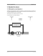
3.1. Differential current detection.................................................................................................................. 7
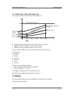
3.1.1. Differential current tripping/warning .............................................................................................. 8
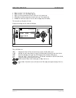
3.2. Display....................................................................................................................................................8
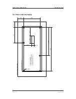
3.2.1. Panel cutout for display .............................................................................................................. 10
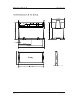
3.2.2. Unit dimensions in mm (inches)...................................................................................................11
4. Hardware
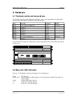
4.1. Terminals and board slot positions....................................................................................................... 12
4.2. Base unit LED indicators...................................................................................................................... 12
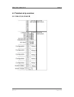
4.3. Terminal strip overview.........................................................................................................................14
4.3.1. Slots #1, #2, #5 and #6 ...............................................................................................................14
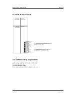
4.3.2. Slots #3, #4, #7 and #8 ...............................................................................................................15
4.4. Terminal strip, explanation....................................................................................................................15
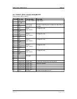
4.4.1. Slot #1, power supply and digital I/O .......................................................................................... 16
4.4.2. Slot #7, AC current measurement .............................................................................................. 17
5. Wiring diagrams
5.1. Coupling and connection......................................................................................................................18
5.1.1. AC current measurements, star coupling.................................................................................... 18
5.1.2. AC current measurements, delta coupling ..................................................................................19
5.1.3. DC connections, inputs and outputs ...........................................................................................20
6. Parameter programming
6.1. Programming........................................................................................................................................21
6.1.1. About programming..................................................................................................................... 21
6.1.2. Parameter setting method in display .......................................................................................... 21
6.2. Differential current................................................................................................................................ 21
6.2.1. Settings .......................................................................................................................................21
6.2.2. Warning (curve 1) ....................................................................................................................... 22
6.2.3. Trip (curve 2) .............................................................................................................................. 22
6.2.4. Trip (fixed trip value) ................................................................................................................... 23
6.2.5. Use of relay outputs ....................................................................................................................23
6.3. Other settings....................................................................................................................................... 23
6.3.1. Status LED ..................................................................................................................................23
6.3.2. Auto acknowledgement of alarms ...............................................................................................23
6.3.3. Service menu ..............................................................................................................................24
6.4. Nominal settings...................................................................................................................................24
6.4.1. Nominal current .......................................................................................................................... 24
6.4.2. Current transformers ...................................................................................................................24
6.4.3. Date and time (internal clock) .....................................................................................................25
6.4.4. Power supply (battery) under-voltage alarm ...............................................................................25
MDR-2 DRH 4189340300 UK
DEIF A/S
Page 2 of 26


