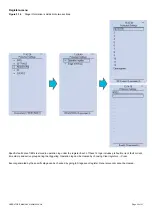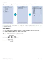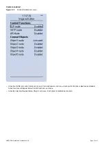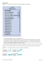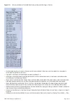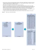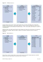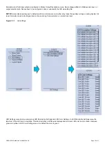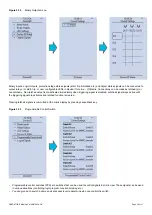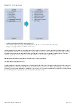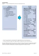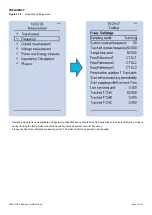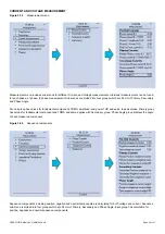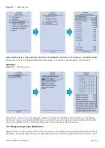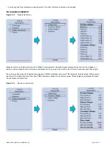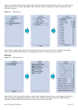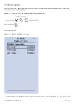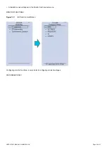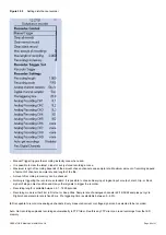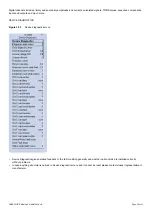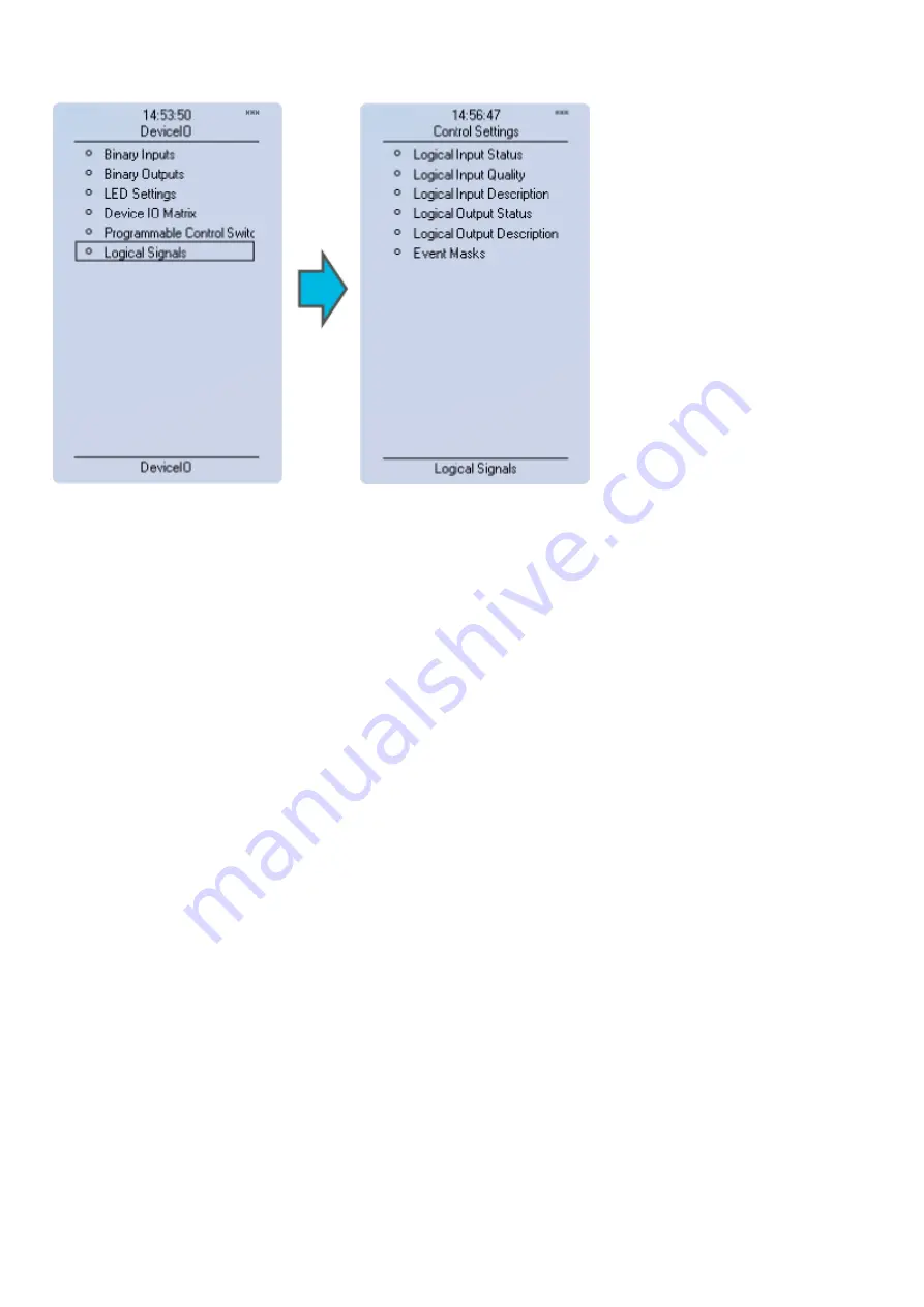
Figure 3.34
IED Logical signals.
•
32 logical input signal status bits. Status is either 0 or 1.
•
32 quality bits of logical input signals (GOOSE). Status is either 0 or 1. 1 stands for bad/invalid quality.
•
32 logical output signal status bits. Status is either 0 or 1.
Logical signals are mainly used for control purposes via IEC-61850 and GOOSE or other protocols with similar purpose. Logical
Inputs Quality bit checks the condition of logical input. Logical Outputs can be used when building programmable logic. Activating
logic gate won’t make event but when logical output is connected to the logic gate it is possible to create an event of the gate
activation. Logical inputs and outputs have on and off events those can be masked on (off as default).
NOTE!
System integration chapter gives more details of use of the logical signals.
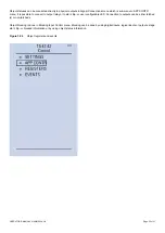
3.4.5 Communication menu
Communication menu includes
Connections
and
Protocols
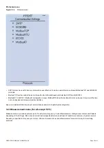
sub-menus. IEDs can be configured through rear Ethernet by using the
MVR Utility Software. IP address of the IED can be checked from the Connections menu. IEDs support following communication
protocols: SNTP, IEC61850, ModbusTCP, ModbusRTU, IEC103, IEC101/104, SPA and ModbusIO as a standard. It is also possible
to have additional protocols with special extra communication interface modules.
OPERATOR'S MANUAL 4189341220A UK
Page 37 of 51


