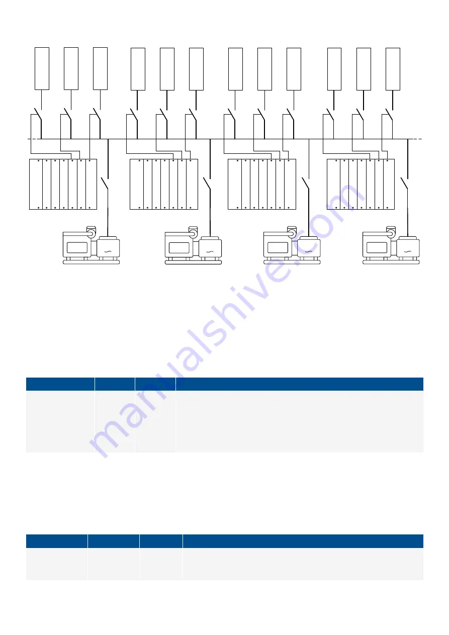
Figure 4.7
Example of 12 non-essential loads that are connected with no redundancy
G
G
N
E
L
1
N
E
L
2
N
E
L
3
N
E
L
1
N
E
L
2
N
E
L
3
N
E
L
1
N
E
L
2
N
E
L
3
N
E
L
1
N
E
L
2
N
E
L
3
G
G
DEIF recommends that you connect each non-essential load to each controller, so that any controller can trip the non-essential
loads. As a minimum, each non-essential load should be connected to at least two controllers. However, it is possible to connect
each controller to up to three non-essential loads, with no interaction from the other controllers.
Inputs and outputs
Assign the non-essential load inputs and outputs under
Configure > Input/output
for each controller. Select the hardware module,
then select the input/output to configure.
Table 4.17
Hardware required in addition to the minimum standard controller wiring
Function
I/O
Type
Details
Non-essential load
trip > Non-essential
load trip #
Digital
output
Continuous
The controller activates the output when a non-essential load alarm is activated.
The digital output will be activated as long as at least one NEL alarm is active.
That is, if the operating value no longer exceeds the set point, the digital output
is normally deactivated. However, if an NEL alarm has a latch, the digital output
will not be deactivated until latch is reset.
Parameters
The non-essential load parameter is only visible when the
Non-essential load trip #
function is configured.
Configure this parameter under
Configure > Parameters > Non-essential load trip > Trip # > Settings
, where # is 1, 2 or 3.
Table 4.18
Non-essential load parameter
Parameter
Range
Default
Notes
Trip when breaker
trips
Not enabled,
Enabled
Not enabled
Not enabled
: Controller breaker trips have no direct effect on the non-
essential load trips.
DESIGNER'S HANDBOOK 4189340911K UK
Page 119 of 521


