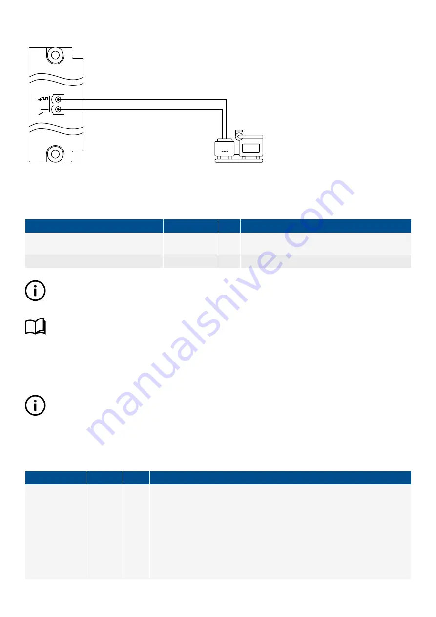
Figure 6.7
Example of pulse width modulation analogue output wiring for AVR regulation
Regulators > AVR > AVR output [%]
G
Inputs and outputs
You must assign the AVR regulation analogue output under
Configure > Input/output
. Select the hardware module, then select an
analogue output to configure.
Function
I/O
Type
Details
Regulators > AVR > Command > Reset AVR
to offset
Digital input
Pulse
When the operator activates this digital input, the output
is set to the offset value.
Regulators > AVR > AVR output [%]
Analogue output
The controller adjusts this output to regulate the AVR.
INFO
The setup and parameters for AVR regulation using pulse width modulation (PWM) is exactly the same as for an analogue
output.
More information
See
Input/Output
,
Tasks
,
Configure the output setup
in the
PICUS manual
for more information about how to configure
an analogue output.
Parameters
You can configure the AVR analogue control parameters under
Configure > Parameters > Regulators > AVR analogue
configuration
.
INFO
To see the AVR analogue control parameters, you must assign the
Regulators > AVR > AVR output [%]
function to an
analogue output (that is, AO or PWM).
Offset
When you start and/or run a genset, you might want to adjust the starting point for analogue regulation. This is done by changing the
output offset.
Parameter
Range
Default Notes
AVR output offset 1
AVR output offset 2
AVR output offset 3
AVR output offset 4
-100 to
100 %
0 %
The offset is added to the AVR analogue output. The number of the offset relates to the
nominal settings set. If you select
Nominal settings 1
, then the controller uses
AVR
output offset 1
. The nominal settings set also determine the values of other nominal
settings and engine RPM.
When the genset is started, it will start from the offset value, allowing the genset to
reach the set point quickly. Ideally, the AVR should be tuned so that if there is no signal,
the genset runs at its nominal voltage if there is no load. However, if this is not possible,
AVR output offset allows you to compensate the output to the AVR.
DESIGNER'S HANDBOOK 4189340911K UK
Page 199 of 521


