Figure 7.3
Example of busbar sections created by closing a bus tie breaker and an externally controlled bus tie breaker
Bus tie
breaker 2
Bus tie
breaker 1
BUS TIE
breaker
controller
BUS TIE
breaker
controller
Externally controlled
bus tie breaker 1
Externally controlled
bus tie breaker 2
Section 1-2-3
Section 1-2-3
Section 1-2-3
Section 4
Busbar A
Busbar B
Busbar A
Busbar B
You can use CustomLogic to set conditions to determine the power management rules for a section. Alternatively, you can configure
digital inputs to determine the power management rules for a section.
INFO
The busbar sections are numbered here to make it easier to understand sections. However, busbar section numbers are
not used in PICUS. When CustomLogic is used to set the power management rules for one controller in the section, then
all the controllers in that section start to use the same power management rules.
More information
See
Power management
,
Power management principles
,
Section power management
for more information about the
power management rules for each busbar section.
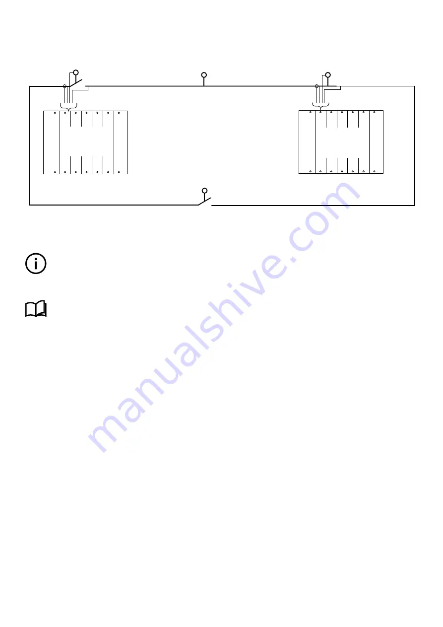
7.1.4 Ring busbar connection
BUS TIE breaker controllers and/or externally controlled bus tie breakers can be installed in system with a ring busbar, as shown in
the following example.
DESIGNER'S HANDBOOK 4189340911K UK
Page 212 of 521


